Dehydrohalogenation reactor and process
A dehydrohalogenation and reactor technology, applied in the field of electric heating reactors, can solve the problems of heat transfer surface coking, efficiency loss, large molten salt flow, etc.
- Summary
- Abstract
- Description
- Claims
- Application Information
AI Technical Summary
Problems solved by technology
Method used
Image
Examples
Embodiment 1
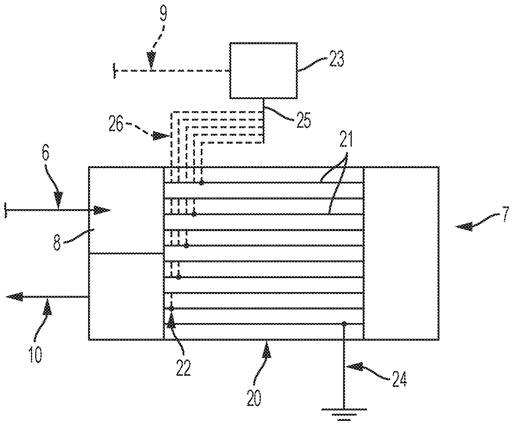
[0068] In this example, a thermally insulated 1" x 0.065" Inconel 625 tubular reactor was used, with a 7-point thermocouple inserted into the inside of the tube with a 1 / 8" OD. The distance between two adjacent temperature probe points was 4″. The reactor serves as a pressure vessel, heating element and heat transfer surface. A Flex Kraft rectifier with a maximum output of 5 V and 140 A was used to provide DC (direct current) power to the Inconel 625 reactor. Once the hot spot temperature of the reactor reached its setpoint, the flow of the 244bb feed was started. During the course of the reaction, the reactor effluent was periodically sampled for its composition.
[0069] Table 1 lists their average reactivity under various conditions. Higher activity was observed in this impedance heater reactor than in conventional (externally heated) reactors. For example, near 30% conversion of 244bb is achieved at temperatures below 450°C. In addition, as shown in Table 1, the selec...
Embodiment 2
[0075] The same reactor and setup as described in Example 1 was used in Example 2. A speed test was performed by doubling the feed rate. In one experiment, the feed rate was doubled, but the DC input power was kept the same (2.57V / 118.2A). As shown in Table 2, doubling the feed rate resulted in a significant decrease in both hot spot temperature (~468°C down to ~453°C) and 244bb conversion (~39% down to ~11%). However, both the hot spot temperature and the 244bb conversion increase with increasing input power. As shown in Table 2, at 2.76V / 126.2A, the hot spot temperature and 244bb conversion increase to ~483°C and ~40%, respectively. In conclusion, comparable 244bb conversions were achieved by increasing the electrical input power by about 15% for doubling the feed rate.
[0076] Table 2*
[0077]
[0078] *Organic composition - 0.8GC area% 245cb / 94.9GC area%244bb / 4.1GC area%1233x.
Embodiment 3
[0080] The same reactor and setup as described in Example 1 was used in Example 3. The effect of HCl / HF treatment was studied. By making HCl (or HF) / N 2 The mixed stream was HCl / HF treated by passing through the reactor maintained at high temperature (see Table 3 for conditions). As shown in Table 3, a slightly higher conversion of 244bb was observed after HCl / HF treatment, while the selectivity to 1234yf remained almost unchanged. Note that selective conversion from 1234yf to 1233xf occurs after similar HF treatment in a conventional reactor.
[0081] table 3*
[0082]
[0083] *Organic composition - 0.8GC area%245cb / 94.9GC area%244bb / 4.1GC area%1233x
[0084] # Calculated assuming no 244bb dehydrofluorination occurred.
PUM
 Abstract
Description
Claims
Application Information
 - R&D
- Intellectual Property
- Life Sciences
- Materials
- Tech Scout
- Unparalleled Data Quality
- Higher Quality Content
- 60% Fewer Hallucinations
Browse by: Latest US Patents, China's latest patents, Technical Efficacy Thesaurus, Application Domain, Technology Topic, Popular Technical Reports.
© 2025 PatSnap. All rights reserved.Legal|Privacy policy|Modern Slavery Act Transparency Statement|Sitemap|About US| Contact US: help@patsnap.com


