
Handle assembly and electric toothbrush

A technology of components, handles, applied in the direction of dentistry, cleaning teeth, engine components, etc.

Pending Publication Date: 2019-07-23
胡斐凡
View PDF0 Cites 3 Cited by
  • Summary
  • Abstract
  • Description
  • Claims
  • Application Information

AI Technical Summary

Problems solved by technology

[0005] In order to overcome the problem in the prior art that the way of providing axial pressure to tighten the seal is prone to failure and water seepage due to fatigue, etc., the present invention provides a handle assembly and an electric toothbrush

Method used


Image

  • Handle assembly and electric toothbrush
  • Handle assembly and electric toothbrush
  • Handle assembly and electric toothbrush

Examples


Embodiment

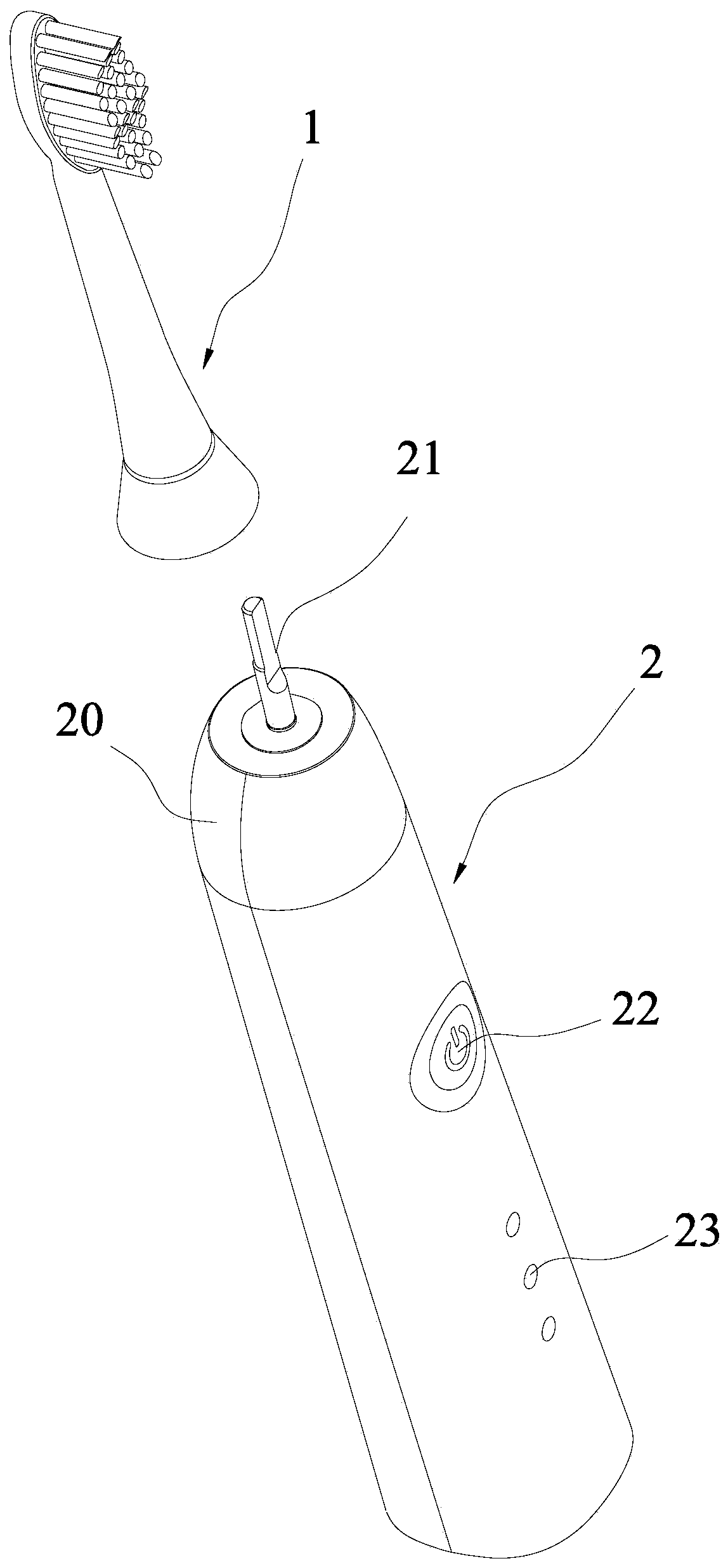
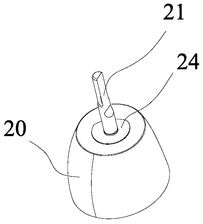
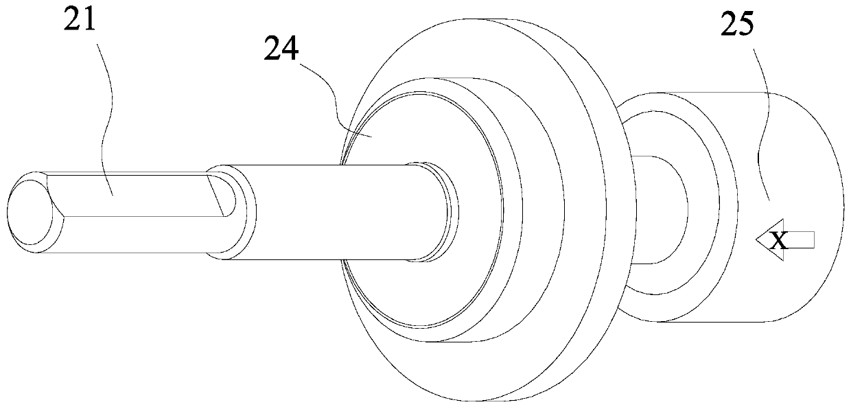
[0052] Such as figure 1 , figure 2 , image 3 As shown, the electric toothbrush disclosed in this example also includes a handle assembly 2 and a brush head assembly 1 . In this example, the toothbrush assembly adopts a technology known to the public, and the brush head assembly 1 can be inserted into the handle assembly 2 . Specifically, it includes a housing 20, a bottom cover, a motor, a battery and a control board; a sealed installation space is formed between the housing 20 and the bottom cover, and the motor, battery and control board are installed in the sealed installation space; A drive shaft 21 is drawn from the motor in the handle assembly 2 ; the brush head assembly 1 is inserted on the drive shaft 21 and is driven by the drive shaft 21 to swing back and forth. The casing 20 is generally provided with a power switch 22, an indicator light 23, and the like, which are not described in detail because they are not part of the improvement in this example. In this ex...


PUM


Abstract

In order to solve the problem that in the prior art, a manner of providing axial pressure to tightly prop a sealing element is adopted, and invalidation and water seepage are easy to cause because ofweariness and the like, the invention provides a handle assembly and an electric toothbrush. According to the handle assembly provided by the invention, a tensioning convex ring is arranged on the inner end surface of the housing, at the head end of the housing, and is in interference fit with a first ring groove on the sealing element, so that a propping piece only needs to exert a small axial pressing force, a large pressing force can be produced in the radial direction between the groove wall of the first ring groove of the sealing element and the tensioning convex ring, and sealing betweenthe tensioning convex ring and the inner wall of the housing is realized through elastic extruding exerted on the sealing element in the radial direction by the tensioning convex ring; and therefore,a long winding sealing path is also produced, and the situation that seeped water cannot enter the handle assembly is guaranteed.

Description

technical field [0001] The invention relates to the field of electric toothbrushes, in particular to a three-dimensional schematic diagram of a seal on a handle assembly. Background technique [0002] well known, such as figure 1 As shown, the electric toothbrush includes a handle assembly 2 and a brush head assembly 1, and the handle assembly 2 includes a housing 20, a bottom cover (not marked in the figure) and a battery built in the sealed space formed by the housing 20 and the bottom cover , a motor, a control board, etc., and a drive shaft 21 is sealed and protruded from the front end (or top end) of the housing 20 , and the drive shaft 21 is detachably connected with the brush head assembly 1 . When using an electric toothbrush, the drive shaft 21 of the handle assembly 2 swings back and forth at high frequency along the axis, driving the brush head assembly 1 inserted thereon to swing back and forth, driving the bristles on the brush head assembly 1 to swing to clean...

Claims


Application Information

Patent Timeline
IPC IPC(8): A61C17/22A61C17/34F16J15/3268F16J15/3284
CPCA61C17/3481A61C17/225F16J15/3268F16J15/3284
Inventor 胡斐凡胡斐然胡建坤
Owner 胡斐凡
Learn More