Laser welding head

A laser welding head and welding head technology, applied in laser welding equipment, welding equipment, metal processing equipment, etc., can solve the problems of easy damage to the protective mirror, increase the volume of the equipment, and the position of the welding point cannot be adjusted up and down, so as to ensure the welding quality , Avoid molten pool oxidation, convenient and quick adjustment process

Active Publication Date: 2019-07-23
深圳市慧之光科技有限公司
View PDF9 Cites 3 Cited by
  • Summary
  • Abstract
  • Description
  • Claims
  • Application Information

AI Technical Summary

Problems solved by technology

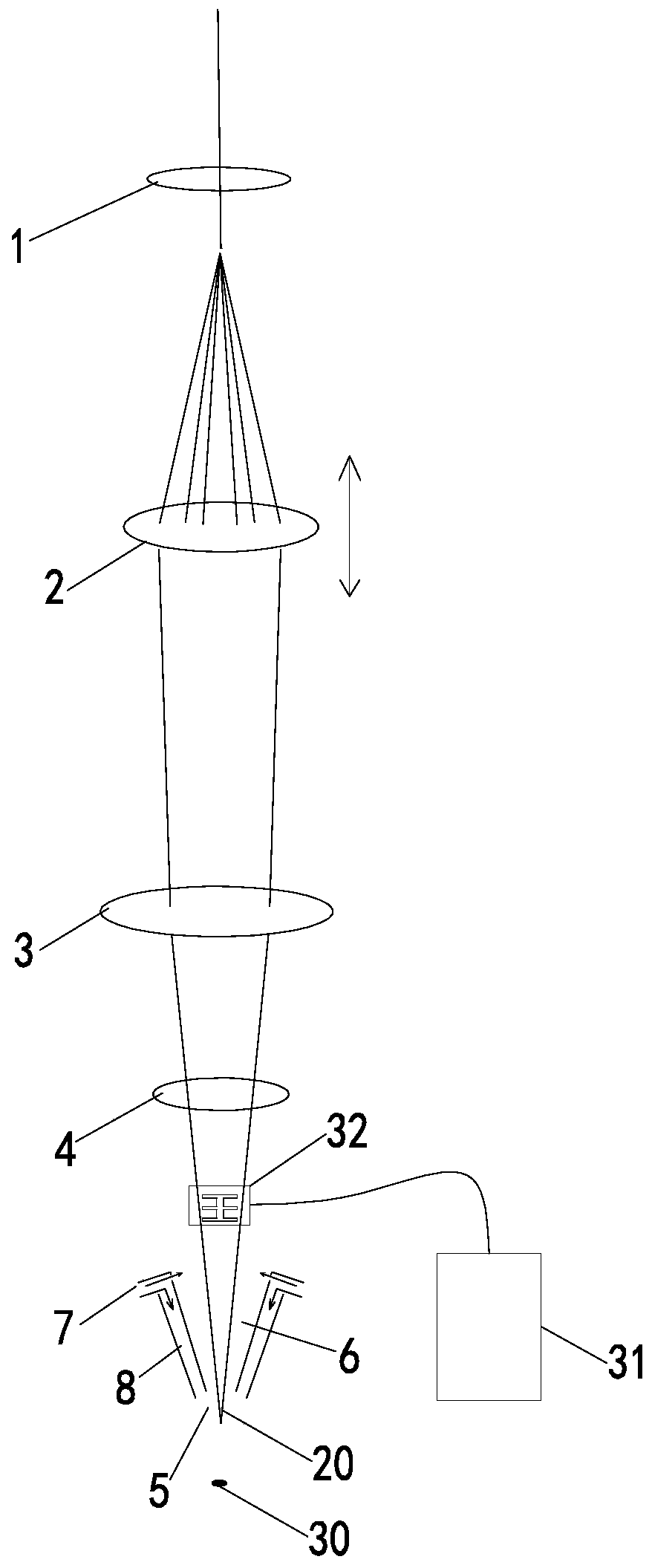
[0007] The technical problem to be solved by the present invention is to provide a laser welding head, which aims to solve the problem that the laser welding head in the prior art needs to be provided with a separate protective gas supply pipeline, which increases the volume of the equipment; the position of the welding spot cannot be adjusted up and down and the protective mirror is easily damaged The problem

Method used


Image

  • Laser welding head
  • Laser welding head
  • Laser welding head

Examples


Embodiment Construction

[0028] In order to make the object, technical solution and advantages of the present invention clearer, the present invention will be further described in detail below in conjunction with the accompanying drawings and embodiments. It should be understood that the specific embodiments described here are only used to explain the present invention, not to limit the present invention.

[0029] In the description of the present invention, it should be noted that the terms "center", "upper", "lower", "left", "right", "vertical", "horizontal", "inner", "outer" etc. The indicated orientation or positional relationship is based on the orientation or positional relationship shown in the drawings, and is only for the convenience of describing the present invention and simplifying the description, rather than indicating or implying that the referred device or element must have a specific orientation, or in a specific orientation. construction and operation, and therefore cannot be constru...


PUM


Abstract

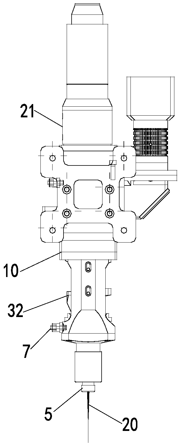
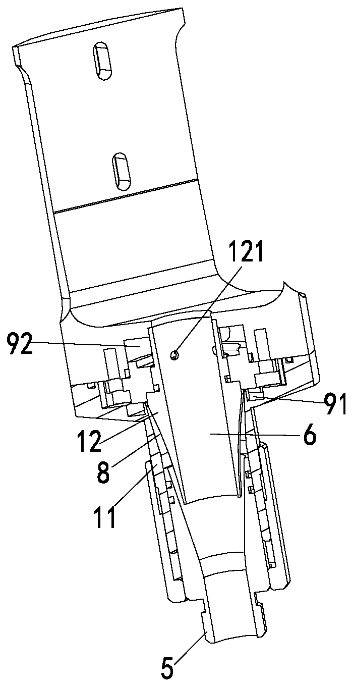
The invention discloses a laser welding head, which comprises a welding head main body, a collimating mirror adjusting mechanism and a blowing device, wherein an optical fiber interface, a collimatingmirror, a focusing mirror, a protective mirror and a nozzle for emitting the laser are arranged in the welding head main body from the top to the bottom; protective gas can be sprayed from a gas channel positioned outside a laser channel, and after being sprayed, the protective gas can align to a welding point accurately, so that the protective gas can cover the welding point quickly, and the oxidation of a molten pool can be prevented and avoided effectively. The collimating mirror adjusting mechanism can change the welding position of the laser, and the focus can be adjusted slightly upwardor downward according to the condition of a workpiece in real time. The adjustment process is convenient and fast; and the whole laser device or a workpiece placing table with greater volume and weight are not needed to be adjusted. A horizontal air outlet of the blowing device can spray horizontal airflow, which can produce a horizontal cutting effect on smoke, and a vertical air outlet can spray the airflow directly opposite to the center of the smoke, so that the center of the smoke is offset to prevent the smoke from rising straightly; and then the upper protective mirror is effectively protected.

Description

technical field [0001] The invention belongs to the field of laser welding equipment, in particular to a laser welding head. Background technique [0002] Laser welding equipment uses high-energy laser pulses to locally heat the material in a small area. The energy of the laser radiation diffuses to the inside of the material through heat conduction, and the material is melted to form a specific molten pool to achieve the purpose of welding. [0003] The laser beam is easy to focus, align and be guided by optical instruments. It can be placed at an appropriate distance from the workpiece, and can be redirected between the tools or obstacles around the workpiece. Other welding methods cannot be used due to the above-mentioned space constraints. . Second, workpieces can be placed in closed spaces. The laser beam can be focused on a small area, small and closely spaced components can be welded, a wide range of weldable materials can be welded, and various heterogeneous materi...

Claims


Application Information

Patent Timeline
IPC IPC(8): B23K26/21B23K26/14B23K26/04
CPCB23K26/21B23K26/14B23K26/04Y02E60/10
Inventor 刘润军汤壹伍
Owner 深圳市慧之光科技有限公司
Why Eureka
Try Eureka