Composite spherical hinge

A compound ball and hinge technology, applied in the direction of manipulators, manufacturing tools, joints, etc., can solve the problems that cannot be guaranteed to overlap at a fixed point, cannot be guaranteed to be independent of each other, and achieve the effect of convenient processing and manufacturing and simple overall structure

Pending Publication Date: 2019-07-23
尤天宇
View PDF2 Cites 1 Cited by
  • Summary
  • Abstract
  • Description
  • Claims
  • Application Information

AI Technical Summary

Problems solved by technology

[0005] (1) It cannot be guaranteed that all the rotation centers of two or more general ball hinges always coincide with one fixed point;
[0006] (2) It

Method used


Image

  • Composite spherical hinge
  • Composite spherical hinge
  • Composite spherical hinge

Examples


Embodiment 1

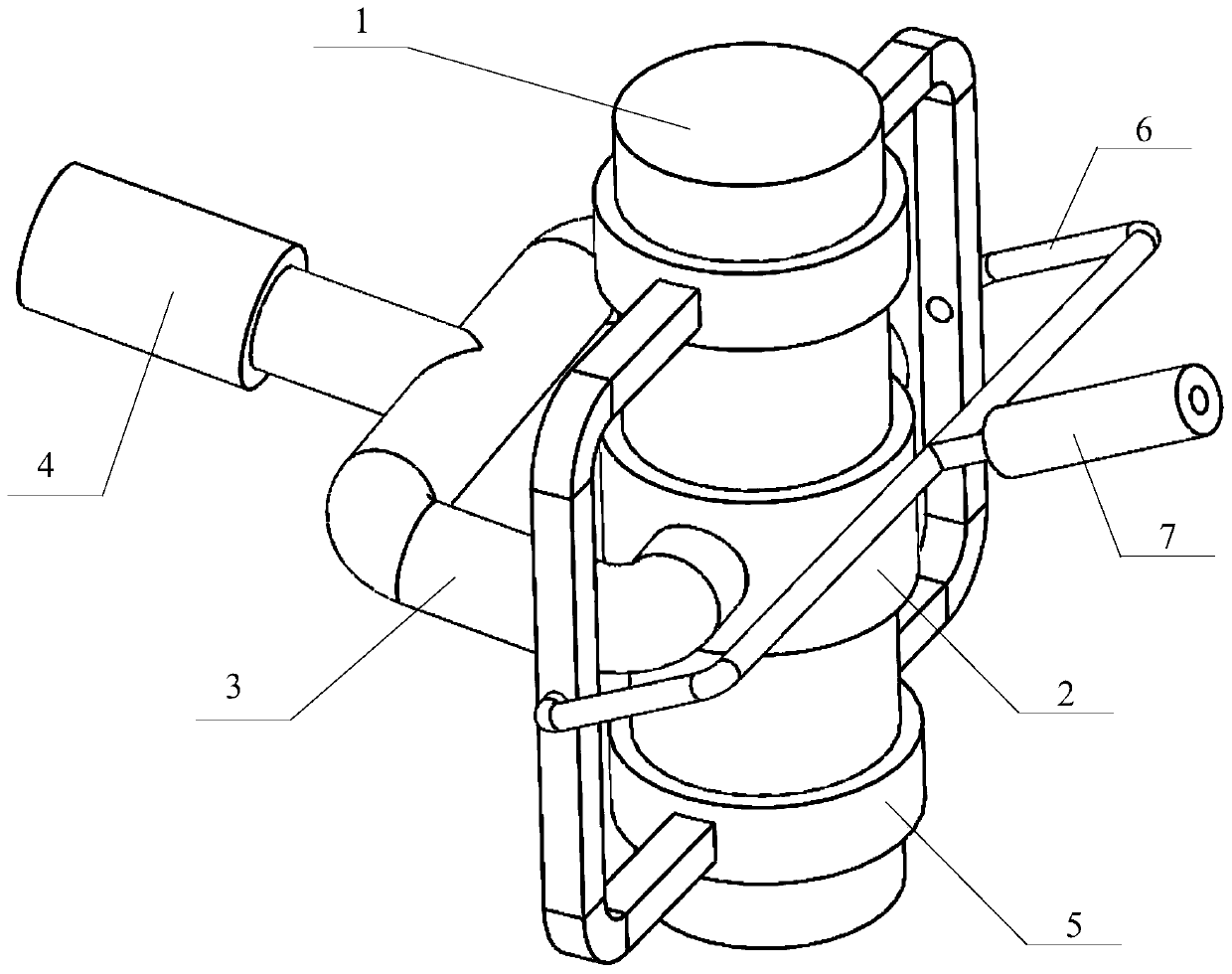
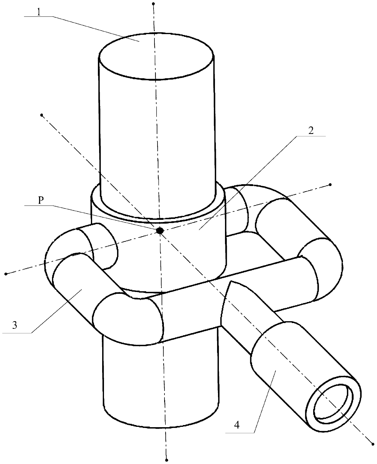
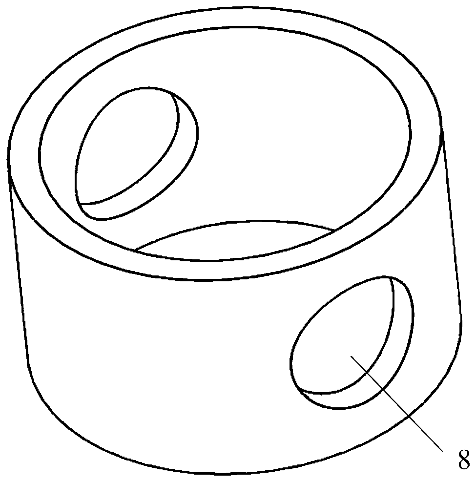
[0032] Such as Figure 1 to Figure 6 As shown, a compound ball hinge includes a central column 1 and a first-layer hinge and a second-layer hinge arranged on the central column 1, the first-layer hinge is arranged between the first member and the second member, and the second-layer The hinge is arranged between the first member and the third member. The first hinge and the second hinge are general ball hinges, both of which have three rotation axes, and the three rotation axes are perpendicular to each other. The three rotation axes of the first hinge always intersect. At the same point P, the three rotation axes of the second-layer hinge always intersect at the same point Q. During actual assembly, point P and point Q coincide. Wherein, the first hinge is composed of a first sleeve 2, an inner fork 3 and a first sliding column 4, the first sleeve 2 is arranged at the middle section of the central column 1, and the inner fork 3 is connected to the first sleeve 2 , the first s...


PUM


Abstract

The invention relates to a composite spherical hinge. The hinge comprises a central column and a first layer hinge and a second layer hinge which are arranged on he central column, the first layer hinge is composed of a first sleeve tube, an inner fork and a first sliding column, the first sleeve tube is arranged in the middle section of the central column, the inner fork is connected with the first sleeve tube, the first sliding column is installed on the inner fork, the second layer hinge is composed of a second sleeve tube, an outer fork and a second sliding column, the second sleeve tube is arranged at the end of the central column, the outer fork is connected with the second sleeve tube, and the second sliding column is installed on the outer fork. The composite spherical hinge has the advantages that the six-degree-of-freedom independent rotation among three components can be synchronously achieved, the range of the rotation angle is wide, all rotation axes intersect at a fixingpoint all the time, the overall structure is simple, symmetric and compact, additional centrifugal inertial force and centrifugal inertial torque are not generated, the processing and manufacturing are convenient, and the composite spherical hinge is suitable for miniature manufacturing.

Description

technical field [0001] The invention relates to a composite ball hinge, in particular to a composite ball hinge widely used in multi-degree-of-freedom and multi-closed-loop motion mechanisms, and belongs to the technical fields of mechanical manufacturing and robots. Background technique [0002] With the coming of the era of artificial intelligence, people's demand for multi-degree-of-freedom and multi-closed-loop motion mechanisms is becoming more and more urgent, especially in the fields of mechanical manufacturing technology and robotics. However, it is very difficult to solve the forward kinematics of the existing multi-degree-of-freedom, multi-closed-loop kinematic mechanism, either there is no full analytical solution, or the calculation efficiency is low. This affects its follow-up work such as dynamic calculation, singular configuration analysis, trajectory planning, and motion control, which in turn restricts the practical application of this type of mechanism in m...

Claims


Application Information

Patent Timeline
IPC IPC(8): B25J17/02
CPCB25J17/0283
Inventor 尤晶晶尤天宇
Owner 尤天宇
Why Eureka
Try Eureka