
Descending linkage self-adjusting annular cutting structure

A self-adjusting and ring cutting technology, applied in metal processing and other directions, can solve problems such as insufficient semi-automation, and achieve the effect of high work efficiency, flexible control and convenience

Active Publication Date: 2019-07-23
玉环大众机械制造有限公司
View PDF8 Cites 1 Cited by
  • Summary
  • Abstract
  • Description
  • Claims
  • Application Information

AI Technical Summary

Problems solved by technology

[0005] The purpose of the present invention is to provide a downward linkage self-adjusting ring cutting structure to solve the need to continuously adjust the radius of the cutting knife when the existing device performs multi-level ring cutting, and at the same time, it is necessary to control the knife out manually. The problem of not using enough semi-automation

Method used


Image

  • Descending linkage self-adjusting annular cutting structure
  • Descending linkage self-adjusting annular cutting structure
  • Descending linkage self-adjusting annular cutting structure

Examples


Embodiment

[0031] as attached figure 1 to attach Figure 6 Shown:

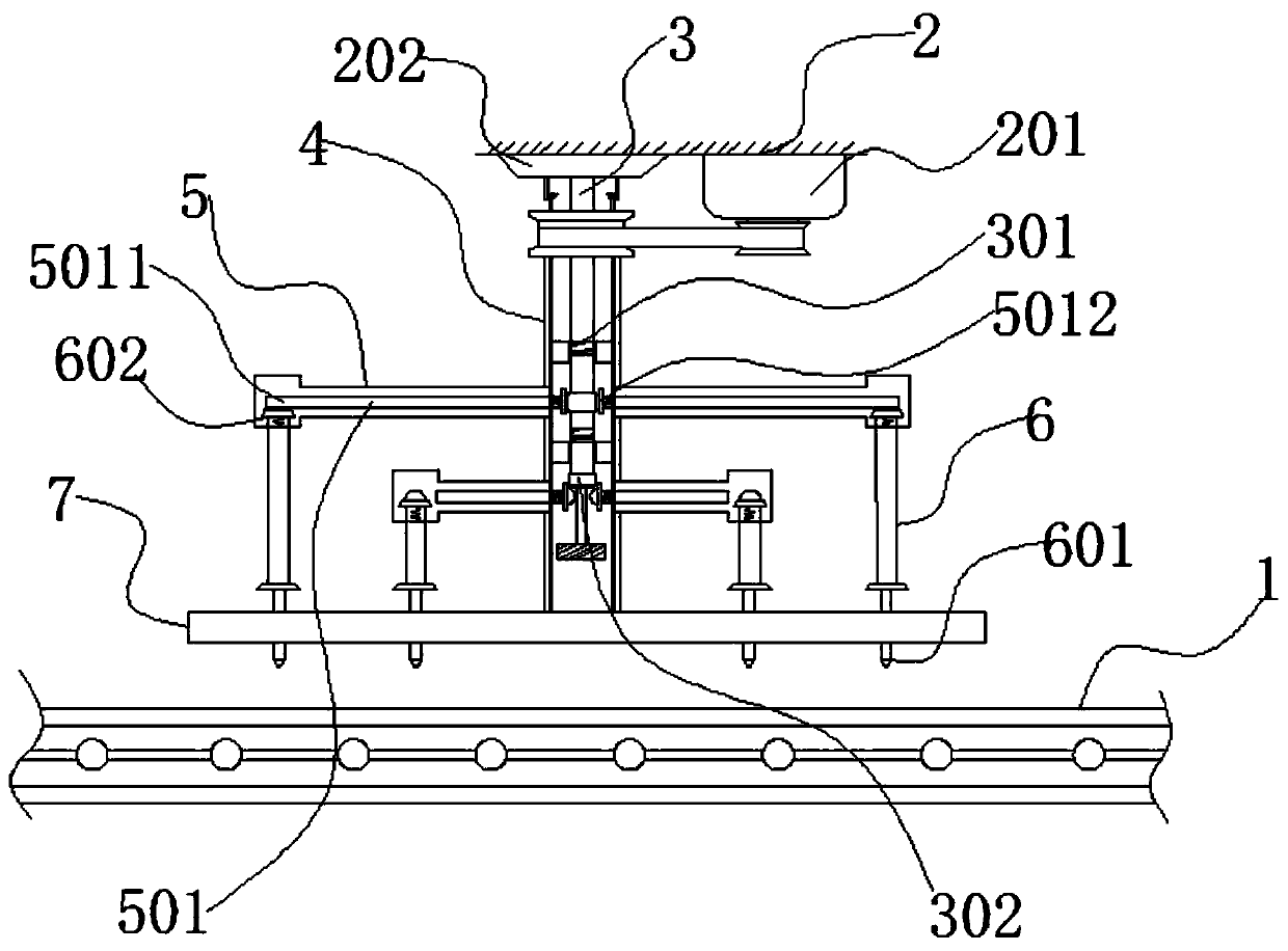
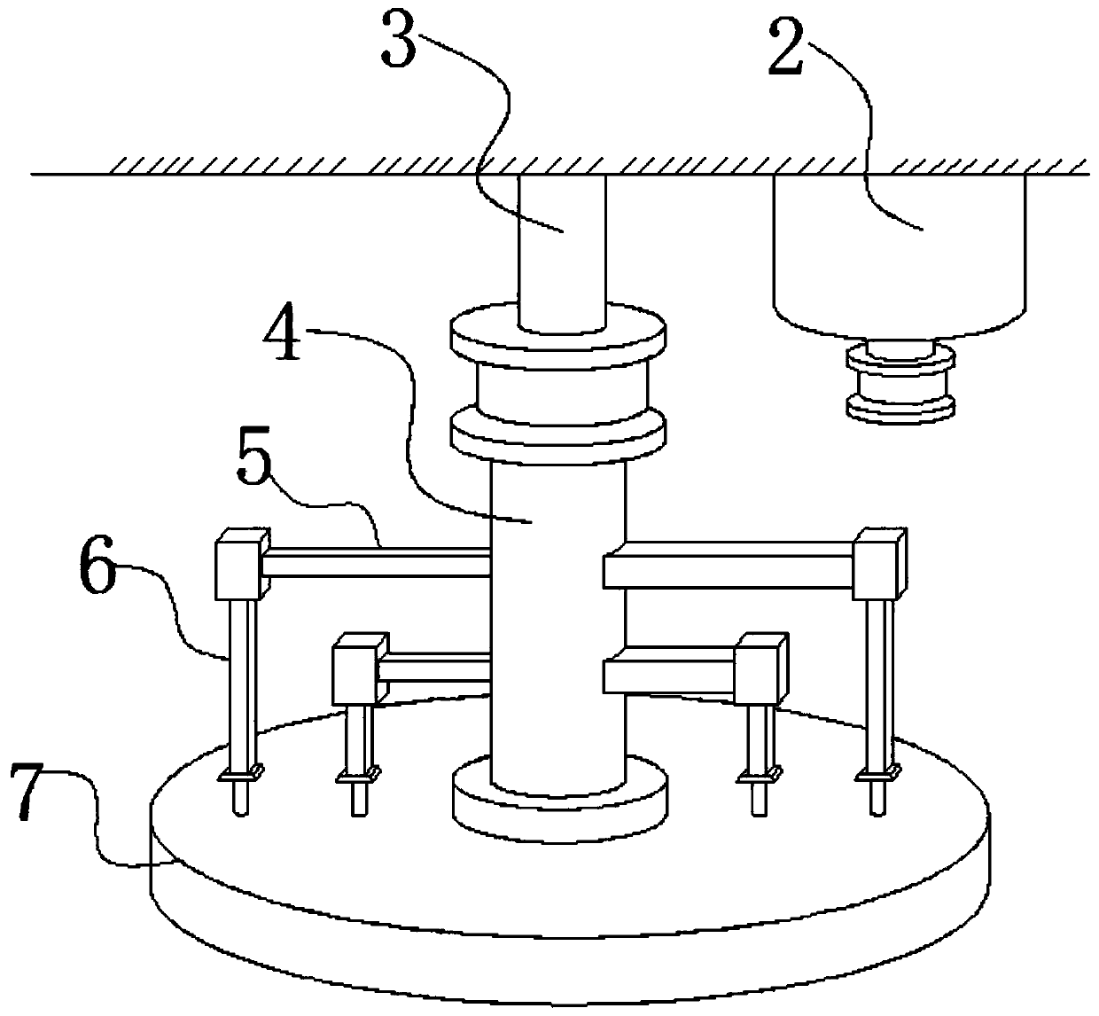
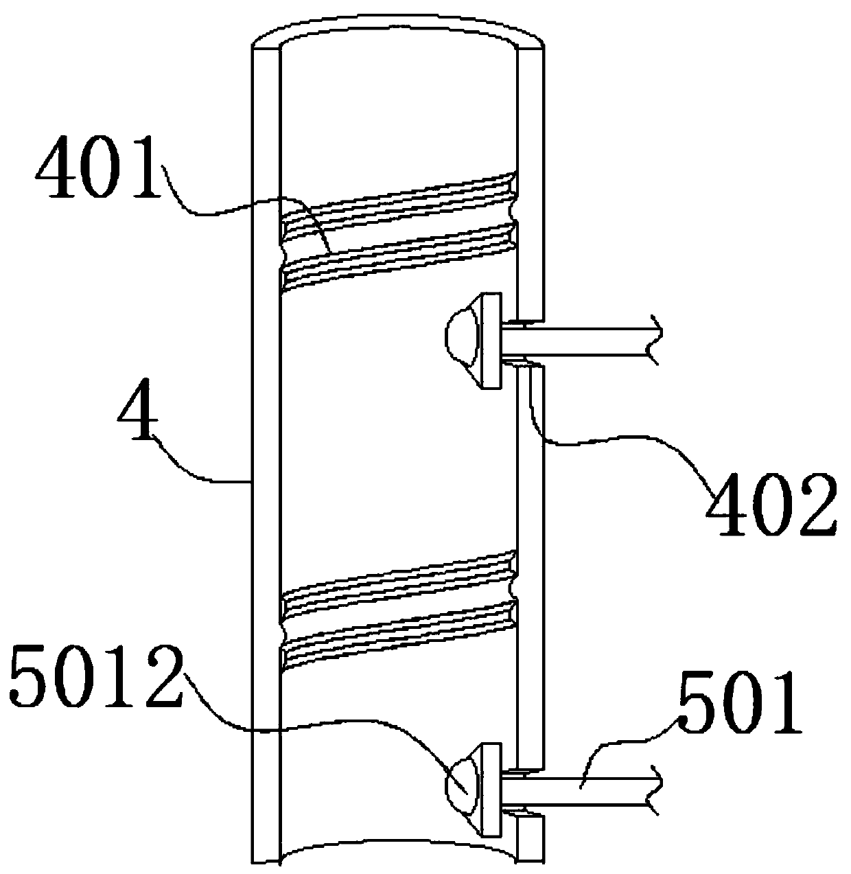
[0032] The present invention provides a downward linkage self-adjusting ring cutting structure, which includes an orientation shaft 3, a telescopic collar 4, a truss plate 5, a longitudinal rod 6, a positioning plate 7, an active sliding wire 301, a raised 302, passive sliding wire 401, Unicom port 402, transmission rod 501, cutting head 601, first passive part 602, pressurization groove 5011 and second passive part 5012; positioning disc 7 is movably connected with longitudinal rod 6, longitudinal rod 6 The upper and lower ends are respectively fixedly connected with the first passive part 602 and the cutting head 601. The first passive part 602 is nested with a truss plate 5, and the truss plate 5 is movably connected with a transmission rod 501, and the two sides of the transmission rod 501 are respectively integrated. A pressurization groove 5011 and a second passive part 5012 are provided, the other side of the tr...


PUM


Abstract

The invention provides a descending linkage self-adjusting annular cutting structure. The descending linkage self-adjusting annular cutting structure comprises an orientation shaft, a telescopic sleeve ring, a truss plate, longitudinal rods, a positioning disc, driving sliding wires, bulges, driven sliding wires, connection openings, driving rods, cutting heads, first driven parts, pressing grooves and second driven parts, wherein the inside of the positioning disc is movably connected with the longitudinal rods; the upper end and the lower end of each longitudinal rod are fixedly connected with a first driven part and a cutting head; when the driven sliding wires are engaged with the driving sliding wires, the overall descending distance of the telescopic sleeve ring is less than the descending distance of the longitudinal rods when the first driven parts are in contact with the pressing grooves. According to the descending linkage self-adjusting annular cutting structure, the overalltelescopic sleeve ring is controlled to move up and down through occlusal contact between threaded sliding wires, so that shrinkage of each group of longitudinal rods is controlled; when the device is used, the device is more flexible and convenient to control; meanwhile, the device is also capable of carrying out operation procedure of reciprocating up and down; the device is more practical; thedevice does not need to be manually controlled and is capable of automatically drawing and withdrawing cutters.

Description

technical field [0001] The invention relates to the field of processing technology, in particular to a downward linkage self-adjusting ring cutting structure. Background technique [0002] Processing is a general term for the process of transforming raw materials and semi-finished products into target needs through certain procedures and methods; [0003] When performing circular cutting on some workpieces, the existing general method is to use a fixed point, and then make the radius change, and then make a circular motion, and then process the workpiece, the common ones are glass cutting, food production and processing Wait. [0004] Based on the above description, and in combination with the equipment in the prior art, it is found that the existing device needs to constantly adjust the radius of the cutting knife when performing multi-level circular cutting. At the same time, it needs to manually control the knife, which is not semi-automatic enough. , so this design aim...

Claims


Application Information

Patent Timeline
Patent Type & Authority Applications(China)
IPC IPC(8): B26D1/28B26D5/08
CPCB26D1/28B26D5/083
Inventor 常倩
Owner 玉环大众机械制造有限公司
Learn More