A face cream preparation system
A technology for preparing systems and creams, which can be applied in the directions of packaging, packaging item types, special packaging items, etc., and can solve the problems of inability to distribute and package the cream
- Summary
- Abstract
- Description
- Claims
- Application Information
AI Technical Summary
Problems solved by technology
Method used
Image
Examples
specific Embodiment approach 1
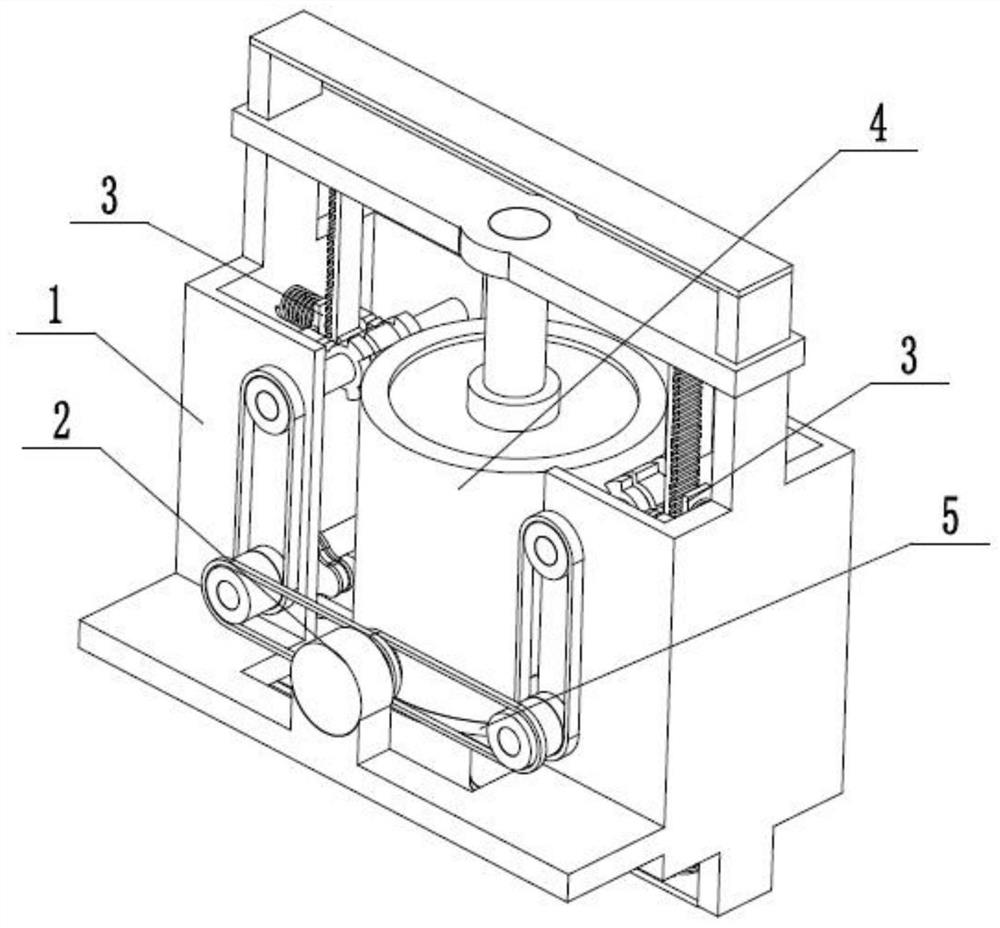
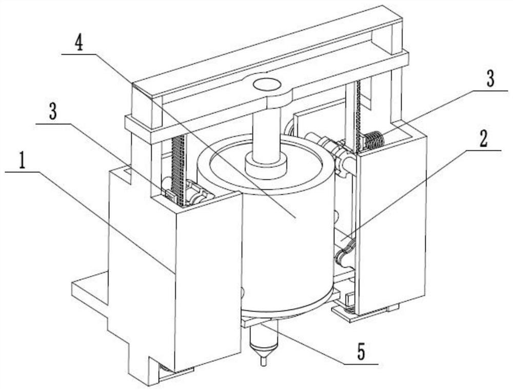
[0032] Such as Figure 1 to Figure 13 As shown, a face cream preparation system includes an adding fixed frame 1, an adding driver 2, two blocking fixing devices 3, a storage adding cylinder 4 and a base stable adding device 5, and the rear end of the adding driver 2 is fixedly connected to the On the added fixed rack 1, the front end of the added driver 2 is rotatably connected in the added fixed rack 1, the upper end of the added driver 2 is slidably connected on the added fixed rack 1, and the left and right ends of the added driver 2 are respectively fixed with two barriers The device 3 fits and drives, and the two blocking and fixing devices 3 are respectively fixedly connected to the left and right ends of the inner wall of the adding fixed frame 1. The upper end of the storage adding cylinder 4 is connected to the adding driver 2 through screw fit, and the lower end of the storage adding cylinder 4 is clearance fit. On the upper end of the base stable adder 5, the upper...
specific Embodiment approach 2
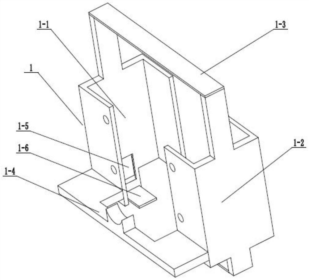
[0033] Such as Figure 1 to Figure 13 As shown, this embodiment will further illustrate Embodiment 1. The described additional fixed frame 1 includes a left fixed frame 1-1, a right fixed frame 1-2, an upper connection plate 1-3, a motor fixed plate 1-4, Two T-shaped inner chutes 1-5 and two fixed bottom plates 1-6, the left and right ends of the upper connecting plate 1-3 are respectively fixedly connected to the left fixed frame 1-1 and the right fixed frame 1-2 On the upper end, the front end of the motor fixing plate 1-4 is fixedly connected to the rear ends of the left fixing frame 1-1 and the right fixing frame 1-2, and two T-shaped inner chute 1-5 are respectively arranged on the inner wall of the left fixing frame 1-1 The left side and the right side of the inner wall of the right fixed frame 1-2, two fixed bottom plates 1-6 are respectively fixedly connected to the lower ends of the left fixed frame 1-1 and the right fixed frame 1-2.
specific Embodiment approach 3
[0034] Such as Figure 1 to Figure 13 As shown, this embodiment will further illustrate the second embodiment. The additional driver 2 includes a servo motor 2-1, a central double-row pulley 2-2, a left double-row pulley 2-3, and a right double-row pulley 2-4. , left drive shaft 2-5, right drive shaft 2-6, two pulleys 2-7, two upper shafts 2-8, two intermittent three-fan drive gears 2-9 and four intermittent three-fan drive discs 2- 10. The servo motor 2-1 is fixedly connected to the motor fixing plate 1-4, the central double-row pulley 2-2 is fixedly connected to the output shaft of the servo motor 2-1, and the central double-row pulley 2-2 passes through the belt The transmission is connected to the left double-row pulley 2-3 and the right double-row pulley 2-4, and the left double-row pulley 2-3 and the right double-row pulley 2-4 are respectively fixedly connected to the left drive shaft 2-5 and the right drive shaft 2-6 The rear end of the left drive shaft 2-5 and the ri...
PUM
 Abstract
Description
Claims
Application Information
 - R&D
- Intellectual Property
- Life Sciences
- Materials
- Tech Scout
- Unparalleled Data Quality
- Higher Quality Content
- 60% Fewer Hallucinations
Browse by: Latest US Patents, China's latest patents, Technical Efficacy Thesaurus, Application Domain, Technology Topic, Popular Technical Reports.
© 2025 PatSnap. All rights reserved.Legal|Privacy policy|Modern Slavery Act Transparency Statement|Sitemap|About US| Contact US: help@patsnap.com


