Automobile gearbox adopting clutch hydraulic shifting method

A kind of automobile gearbox and hydraulic technology, applied in the direction of components with teeth, transmission control, belt/chain/gear, etc., can solve problems such as unsatisfactory, large vibration amplitude of the gear lever, and reduced operating comfort. The blocking process is smooth and smooth, and the transmission process is smooth

Active Publication Date: 2019-12-13
LUAN YONGZHEN GRIZZLY ELECTRICAL & MECHANICAL TECH CO LTD
View PDF6 Cites 0 Cited by
  • Summary
  • Abstract
  • Description
  • Claims
  • Application Information

AI Technical Summary

Problems solved by technology

[0002] Automobile transmission is a set of transmission devices used to coordinate the speed of the engine and the actual driving speed of the wheels. It is used to exert the best performance of the engine. The transmission can generate different speed ratios between the engine and the wheels during the running of the car. Through Shifting gears can make the engine work at its best power performance state. At present, the cars on the market are divided into two types: manual gear and automatic gear. With the direct control mechanism, the driver can directly manipulate the gear lever to toggle the shift control device in the transmission cover to shift gears. However, the gear lever of the direct control mechanism vibrates greatly during the starting and driving of the car, and the frequency is very high. The operating comfort is reduced, and when the position of the transmission is far away from the shift lever, the direct control mechanism of the transmission cannot meet the layout requirements of the car, which has certain limitations. Transmission system that performs gear changes and greatly reduces vibration during gear changes

Method used


Image

  • Automobile gearbox adopting clutch hydraulic shifting method
  • Automobile gearbox adopting clutch hydraulic shifting method
  • Automobile gearbox adopting clutch hydraulic shifting method

Examples


Embodiment Construction

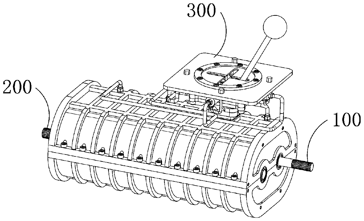
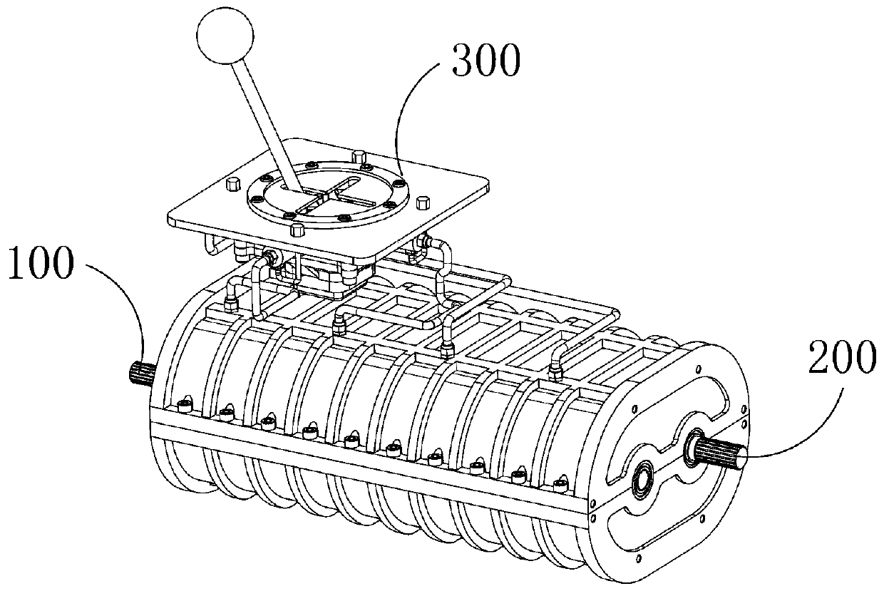
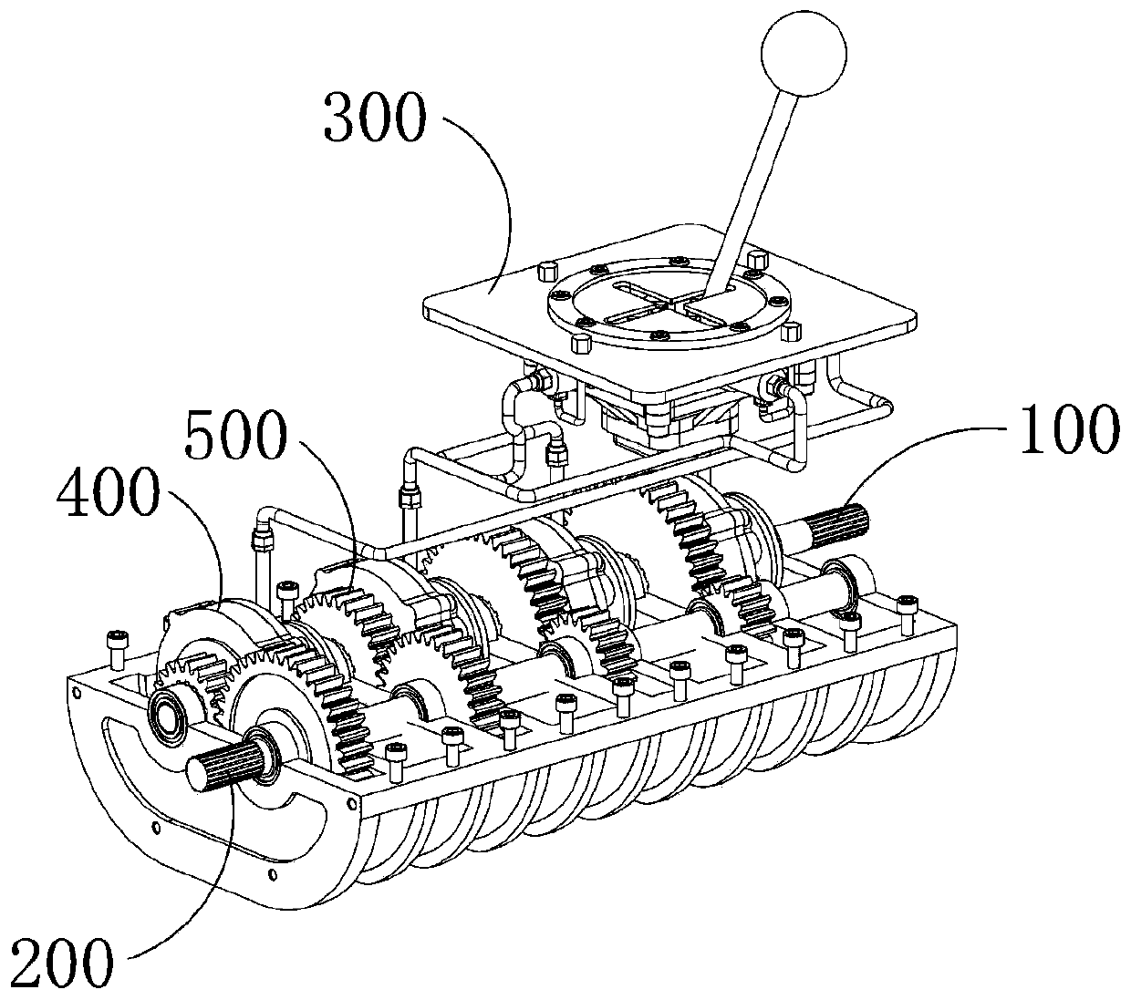
[0066] The present invention has the advantage of adopting the clutch hydraulic method for shifting gears that it can make the shifting process more stable and smooth, and the hydraulic oil transmission method is adopted between the shifting device and the gear device. Compared with the traditional connecting rod linkage transmission method, the transmission The process is smoother. At the same time, the transmission of hydraulic oil can make the installation position selection of the shift device and the gear device in the car more diverse. In addition, during the shifting process of the gear device, the input shaft and the gear mechanism The power transmission is carried out through the clutch, so that the gears in the gear mechanism do not need to be displaced axially, and the gear sets in the gear mechanism have no wear except for the unavoidable wear during meshing rotation, and compared with the transmission gear mechanism, there is no shifting The impact generated by the...


PUM


Abstract

The invention provides an automobile gearbox adopting a clutch hydraulic gear shifting mode. The automobile gearbox comprises an input shaft, an output shaft, a gear shifting device, a gearbox shell and a gear device, wherein the gear shifting device is used for being manually operated by a driver and enabling the gear device to perform gear shifting, the gear device comprises a clutch control mechanism and a gear mechanism, the input shaft and the output shaft are axially parallel, and both are movably arranged in the gearbox shell and can rotate in the axial directions of the input shaft andthe output shaft correspondingly, the power input end of the input shaft extends out of the gearbox shell and is connected with a power system such as an automobile engine, the power output end of the output shaft extends out of the gearbox shell and is connected with an advancing system such as an automobile differential mechanism, the gear mechanism is arranged between the power output end of the input shaft and the power input end of the output shaft, and the clutch control mechanism is used for controlling and determining whether the gear mechanism is capable of receiving the rotating power of the input shaft and transmitting the rotating power to the output shaft or not.

Description

technical field [0001] The invention relates to the field of speed change, in particular to a clutch hydraulic vehicle speed change system. Background technique [0002] Automobile transmission is a set of transmission devices used to coordinate the speed of the engine and the actual driving speed of the wheels. It is used to exert the best performance of the engine. The transmission can generate different speed ratios between the engine and the wheels during the running of the car. Through Shifting gears can make the engine work at its best power performance state. At present, the cars on the market are divided into two types: manual gear and automatic gear. With the direct control mechanism, the driver can directly manipulate the gear lever to toggle the shift control device in the transmission cover to shift gears. However, the gear lever of the direct control mechanism vibrates greatly during the starting and driving of the car, and the frequency is very high. The opera...

Claims


Application Information

Patent Timeline
Patent Type & Authority Patents(China)
IPC IPC(8): F16H59/02
CPCF16H59/02
Inventor 梅厚凤
Owner LUAN YONGZHEN GRIZZLY ELECTRICAL & MECHANICAL TECH CO LTD
Why Eureka
Try Eureka