Supercharge Your Innovation With Domain-Expert AI Agents!

Novel oil seal

A new type of oil seal technology, applied in engine seals, engine components, mechanical equipment, etc., can solve problems such as large friction temperature rise and friction torque, accelerate lip and shaft wear, reduce oil seal life, etc., to achieve lower requirements and lower Oil seal sealing requirements, the effect of simple structure

Pending Publication Date: 2019-07-23
江苏常众发动力有限公司
View PDF0 Cites 0 Cited by
  • Summary
  • Abstract
  • Description
  • Claims
  • Application Information

AI Technical Summary

Problems solved by technology

Therefore, a large friction force will be generated between the lip and the rotating shaft, resulting in the following defects: one is to accelerate the wear of the lip and the shaft and reduce the life of the oil seal; the other is to generate a large friction temperature rise and friction torque, which consumes extra In order to improve wear resistance and service life, generally only replaceable rubber materials can be used, such as nitrile rubber upgraded to fluorine rubber or even better composite materials, but the cost is greatly increased; at the same time, the design according to the above principles The oil seal is also limited by the installation eccentricity and the amount of shaft runout, so it must be used under the condition of improving the manufacturing and assembly accuracy of parts

Method used


Image

  • Novel oil seal
  • Novel oil seal
  • Novel oil seal

Examples


Embodiment 1

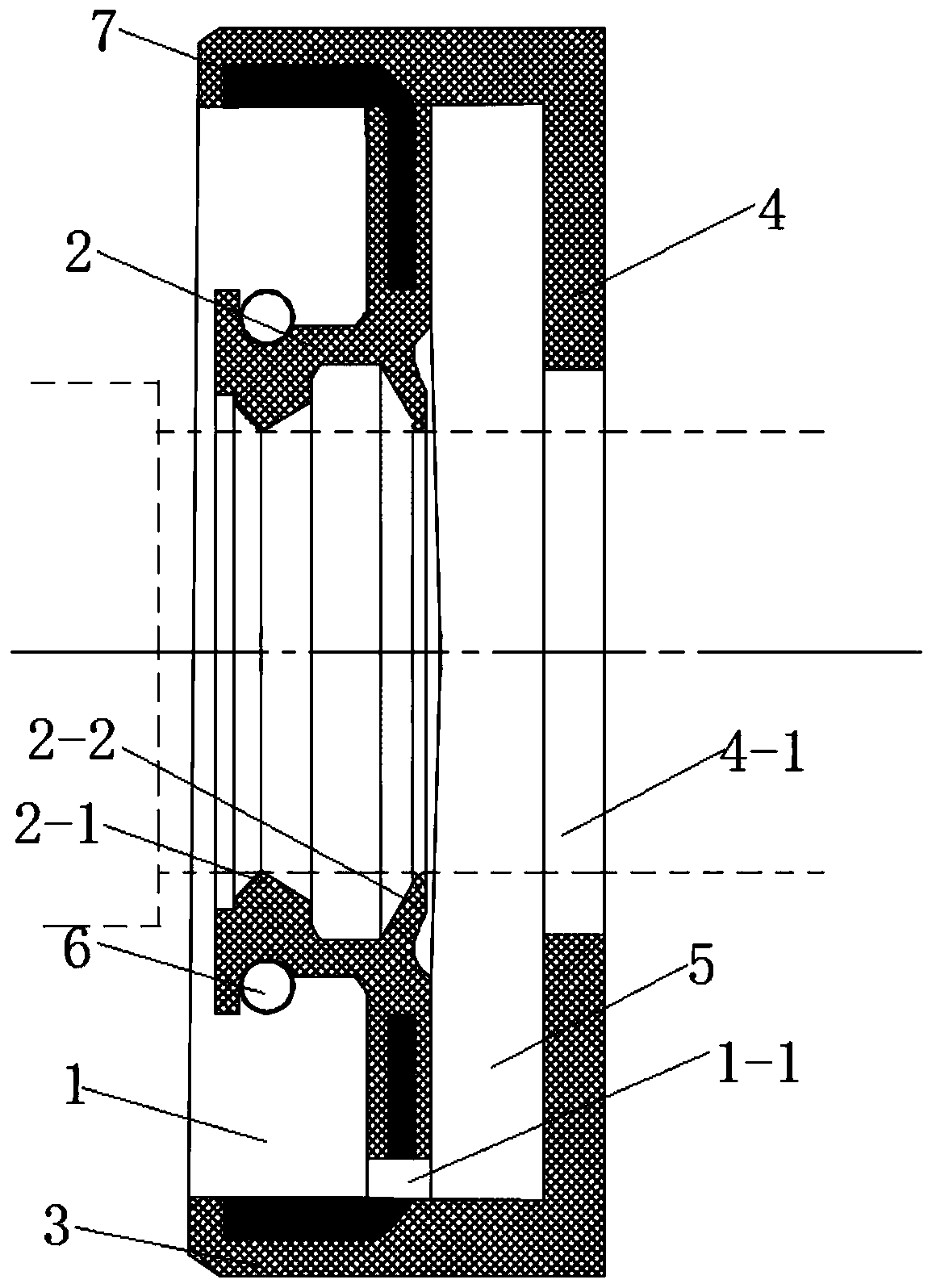
[0023] combine figure 1 , a new type of oil seal of the present invention, comprising an oil seal body, the oil seal body is an annular structure with a U-shaped groove 1 on the end surface, and an inner ring 2 is formed on the oil seal body to hold tightly on the rotating shaft and is used to fit and install in the shaft hole The inner outer ring 3 and inner ring 2 are provided with at least one protruding ring-shaped sealing lip 2-1; the outer ring surface of the inner ring 2 is provided with an annular spring mounting groove. A spring 6 that acts as a clamp is installed in the annular spring installation groove; a dust-proof lip 2-2 for contacting with the rotating shaft and sealing is provided on the inner circular surface of the inner ring 2; the outer ring 3 and the U-shaped groove The inside of the groove bottom of 1 is inlaid with a metal skeleton 7; the bottom of the U-shaped groove 1 is provided with an oil return hole 1-1; the outer surface of the groove bottom of t...

Embodiment 2

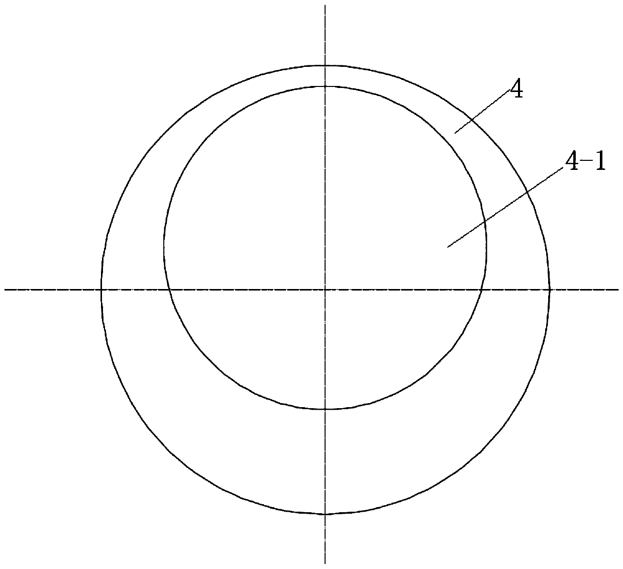
[0025] combine figure 2 with image 3 , the basic structure of a new type of oil seal of the present invention is the same as that of Embodiment 1, the difference is that the cover body 4 is in a circular structure, and the bottom wall of the cover body 4 is provided with an eccentric setting that does not hinder the assembly of the oil seal body on the rotating shaft. Hole 4-1 saves manufacturing materials while ensuring the normal operation of the secondary reflow "seal" structure.

Embodiment 3

[0027] combine image 3 , The basic structure of a new type of oil seal of the present invention is the same as that of Embodiment 1, the difference is that the cover body 4 is in an inferior arc shape, which further saves manufacturing materials while ensuring the normal operation of the secondary return "seal" structure.

[0028] A new type of oil seal of the present invention has a simple structure and ingenious design. Two seals are designed on the oil seal by using the design concept of combination of escapement and escapement, and the second open seal is activated when the first closed seal fails. , to achieve a "seal" that never leaks oil. In addition, due to the existence of the second open seal, it also greatly reduces the requirements for the manufacture of hermetic seals for oil seals, and greatly reduces the manufacturing cost.


PUM


Abstract

The invention discloses a novel oil seal which comprises an oil seal body. The oil seal body is of an annular structure with a U-shaped groove formed in the end face, an inner ring for being clamped to a rotating shaft and an outer ring for being installed in a shaft hole in a matched mode are formed in the oil seal body, an oil return hole is formed in the groove bottom of the U-shaped groove, acover body which can cover the oil return hole and does not prevent the oil seal body from being assembled on the rotating shaft is integrally formed on the outer side surface of the groove bottom ofthe U-shaped groove, and an oil collecting groove communicating with the oil return hole is formed between the bottom wall of the cover body and the groove bottom of the U-shaped groove. Two seals aredesigned on the oil seal by utilizing the design concept of catching-escapement combination and looseness without miss, the second open seal is started when the first closed seal fails, so that sealing without oil leakage is realized. In addition, due to the existence of the second open seal, the requirement for the closed seal manufacturing of the oil seal is greatly lowered, and the manufacturing cost is greatly reduced.

Description

technical field [0001] The present invention relates to an oil seal, more specifically, to a novel oil seal. Background technique [0002] At present, the principle of high-speed rotary oil seal used in domestic engines is to use the high elasticity of rubber to make the lip of the oil seal have a large radial holding force on the shaft, so that the lip of the oil seal is always close to the surface of the shaft. And maintain the tight force, to achieve sealing. Therefore, a large friction force will be generated between the lip and the rotating shaft, resulting in the following defects: first, the wear of the lip and the shaft is accelerated, and the life of the oil seal is reduced; second, a large friction temperature rise and friction torque are generated, which consume extra In order to improve wear resistance and service life, generally only replaceable rubber materials can be used, such as nitrile rubber upgraded to fluorine rubber or even better composite materials, ...

Claims


Application Information

Patent Timeline
IPC IPC(8): F16J15/3208F16J15/3216F16J15/3232F16J15/3252F16J15/3284
CPCF16J15/3208F16J15/3216F16J15/3232F16J15/3252F16J15/3284
Inventor 程伟
Owner 江苏常众发动力有限公司
Features
  • R&D
  • Intellectual Property
  • Life Sciences
  • Materials
  • Tech Scout
  • Unparalleled Data Quality
  • Higher Quality Content
  • 60% Fewer Hallucinations
Learn More