Device for clamping insulator

A technology of insulators and clamping blocks, applied in cable installation, overhead installation, electrical components, etc., can solve problems such as hidden safety hazards, easy falling off and sliding, and unsatisfactory clamping effect, so as to achieve convenient disassembly and assembly and improve safety. Effect

Active Publication Date: 2019-07-23
ZHUZHOU SUNSHINE ELECTRIC PORCELAIN
View PDF5 Cites 2 Cited by
  • Summary
  • Abstract
  • Description
  • Claims
  • Application Information

AI Technical Summary

Problems solved by technology

[0003] Due to the structure of the insulator with a layered insulating umbrella cover on the outside and the special environment used in high voltage, when the existing clamping device cannot clamp and fix the insulator, the clamping effect is not ideal, and it is easy to fall off and slide. At the same time, it has high potential safety hazards and cannot be applied to different types of insulators. Therefore, a new type of device for clamping insulators has become an urgent problem to be solved.

Method used


Image

  • Device for clamping insulator
  • Device for clamping insulator
  • Device for clamping insulator

Examples


specific Embodiment approach 1

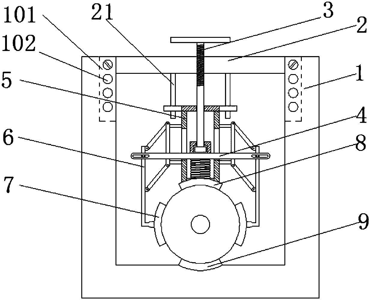
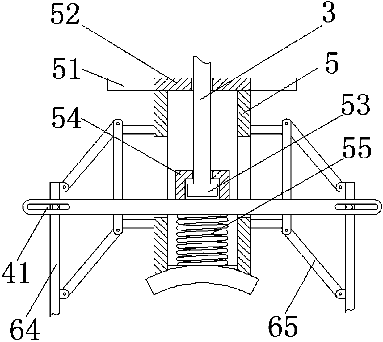
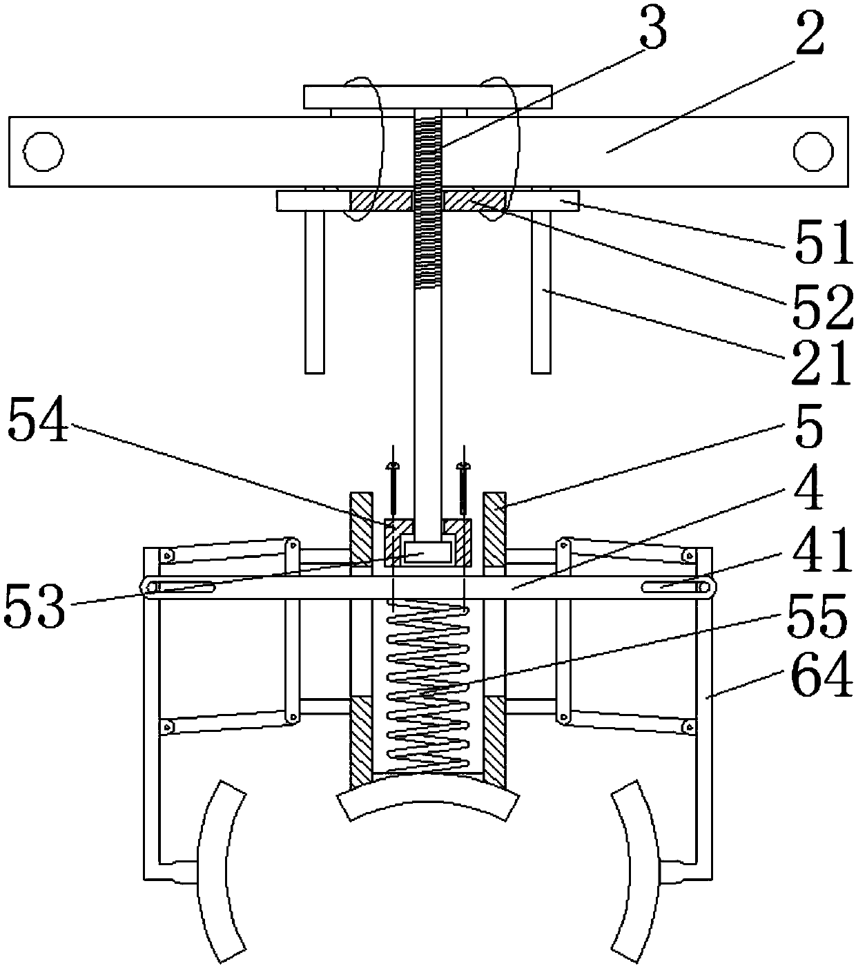
[0032] combine figure 1 and figure 2As shown, a device for clamping insulators disclosed in this embodiment includes: a U-shaped frame 1 and an open cross bar 2. The U-shaped frame 1 includes two vertical side arms, and the inner sides of the two side arms are A chute 101 in the vertical direction is provided, and several positioning holes 102 are arranged at intervals along the vertical direction on the side of the chute 101, which is convenient for adjusting the installation position of the opening cross bar 2. The two ends of the opening cross bar 2 are respectively Inserted into the chute on both sides of the U-shaped frame 1 and fixed by bolts, the lower end of the opening cross bar 2 is provided with two light rods 21 in parallel, the upper ends of the light rods 21 are fixedly connected with the opening cross bar 2, and the light The lower ends of the rods 21 are suspended in the air, and a sleeve slider 51 is arranged on the two light rods 21, and the two sleeve slid...

specific Embodiment approach 2

[0036] This embodiment is based on the specific implementation mode 1, further, in combination with Figure 4 As shown, the connection between the movable rod 64 of the quadrilateral link frame 6 and the side clamping block 7 is a hinged structure, the hinged position of the movable rod 64 is provided with a hinged positioning block 61, and the hinged positioning block 61 is arranged on the movable rod 64 The hinged surface of the side clamping block 7 is facing the side of the side clamping block 7, and the hinged position of the side clamping block 7 is provided with a hinge block slide groove 71 toward the side of the movable rod 64, and the hinge block slide groove 71 is arc-shaped, so The hinged positioning block 61 is arranged in the hinged block slide groove 71 , and a return spring is arranged between both ends of the hinged positioning block 61 and the inner wall of the hinged block slide groove 71 .

[0037] In the process of clamping the insulator by the device, for...

specific Embodiment approach 3

[0039] This embodiment is based on the specific implementation mode 1, further, in combination with Figure 5 As shown, the connection between the movable rod 64 of the quadrilateral link frame 6 and the side clamping block 7 is a hinged structure, and the hinged position of the movable rod 64 is provided with a hinged positioning groove 62, and the hinged positioning groove 62 is in the direction of the hinge axis. The small pit, the hinged position of the side clamping block 7 is provided with a hinged positioning ball 72, the hinged positioning ball 72 is arranged in the positioning ball chute 73, and the positioning ball chute 73 is fixedly connected with the side clamping block 7, A spring is arranged between the hinged positioning ball 72 and the positioning ball chute 73, and the outside of the hinged positioning groove 62 is provided with a reset inclined surface 63, which is a large pit facing the hinge axis.

[0040] In the process of clamping the insulator by the de...


PUM


Abstract

The invention belongs to the technical field of insulator clamping equipment, and particularly relates to a device for clamping an insulator. The device for clamping the insulator comprise an U-shapedframework and an opening cross rod, wherein two ends of the opening cross rod are respectively inserted into sliding grooves in two sides of the U-shaped framework and are fixed by bolts, a screwingrod is arranged at a middle part of the opening cross rod, a lower end of the screwing rod enters a fixed sleeve through a sleeve flange disc and is connected with a fixed block, the fixed block is arranged in a fixed cavity, a lower end of the fixed cavity is connected with a horizontal cross rod, a spring is arranged between the horizontal cross rod and the bottom of the fixed sleeve, a quadrangle connection rod rack is connected with each of two ends of the horizontal cross rod, a side-surface clamping block is hinged with a lower end of the horizontal cross rod, an upper-end clamping blockis arranged at a lower end of the fixed sleeve, a lower-end clamping block is arranged at the bottom of the U-shaped framework, the insulator is not needed to be disassembled during the clamping process, a clamping position is automatically positioned, and a clamping mode having a fixed clamping force and also having a variable clamping force is formed.

Description

technical field [0001] The invention belongs to the technical field of insulator clamping equipment, and in particular relates to a device for clamping insulators. Background technique [0002] An insulator is a device installed between conductors of different potentials or between conductors and ground potential components. It can withstand voltage and mechanical stress. It is a special insulation control that can play an important role in overhead transmission lines. Early During the years, insulators were mostly used on utility poles, and gradually developed into high-voltage wire connection towers where many disk-shaped insulators were hung at one end, called insulating umbrella covers, which were used to increase the creepage distance and were usually made of glass or ceramics; [0003] Due to the structure of the insulator with a layered insulating umbrella cover on the outside and the special environment used in high voltage, when the existing clamping device cannot c...

Claims


Application Information

Patent Timeline
Patent Type & Authority Applications(China)
IPC IPC(8): H02G7/00
CPCH02G7/00
Inventor 闫丽娟
Owner ZHUZHOU SUNSHINE ELECTRIC PORCELAIN
Why Eureka
Try Eureka