
A simulator for simulating conductive slip ring and corresponding simulation method

A conductive slip ring and simulator technology, applied in the field of simulated conductive slip rings and simulators, can solve the problem that the resistance fluctuation of the conductive slip ring cannot be accurately reflected, the instantaneous interruption, the difficulty of simulating the real slip ring, the influence of the accurate transmission of the signal and the effective transmission of energy. And other issues

Active Publication Date: 2021-07-13
SHANGHAI ENG CENT FOR MICROSATELLITES
View PDF0 Cites 0 Cited by
  • Summary
  • Abstract
  • Description
  • Claims
  • Application Information

AI Technical Summary

Problems solved by technology

However, at this stage, wires or signal lines with added interference are usually used to simulate the transmission of electrical energy or electrical signals on conductive slip rings, but they cannot accurately reflect the characteristics of resistance fluctuations and transient interruptions on conductive slip rings, making it difficult to simulate real slip rings.
[0005] The resistance fluctuation caused by the relative rotation of the rotor and stator of the conductive slip ring directly affects the level and signal quality of the transmission line, which is a key indicator affecting the quality of signal transmission; the instantaneous disconnection of the line will directly cut off the signal transmission Level and energy supply, affecting the accurate transmission of signals and the efficient delivery of energy

Method used


Image

  • A simulator for simulating conductive slip ring and corresponding simulation method
  • A simulator for simulating conductive slip ring and corresponding simulation method
  • A simulator for simulating conductive slip ring and corresponding simulation method

Examples


Embodiment Construction

[0046] It should be noted that components in the various figures may be shown exaggerated for the purpose of illustration and are not necessarily true to scale. In the various figures, identical or functionally identical components are assigned the same reference symbols.

[0047] In the present invention, unless otherwise specified, "arranged on", "arranged on" and "arranged on" do not exclude the presence of intermediates between the two. In addition, "arranged on or above" only means the relative positional relationship between two parts, and under certain circumstances, such as after the product direction is reversed, it can also be converted to "arranged under or below", and vice versa Of course.

[0048] In the present invention, each embodiment is only intended to illustrate the solutions of the present invention, and should not be construed as limiting.

[0049] In the present invention, unless otherwise specified, the quantifiers "a" and "an" do not exclude the scen...


PUM


Abstract

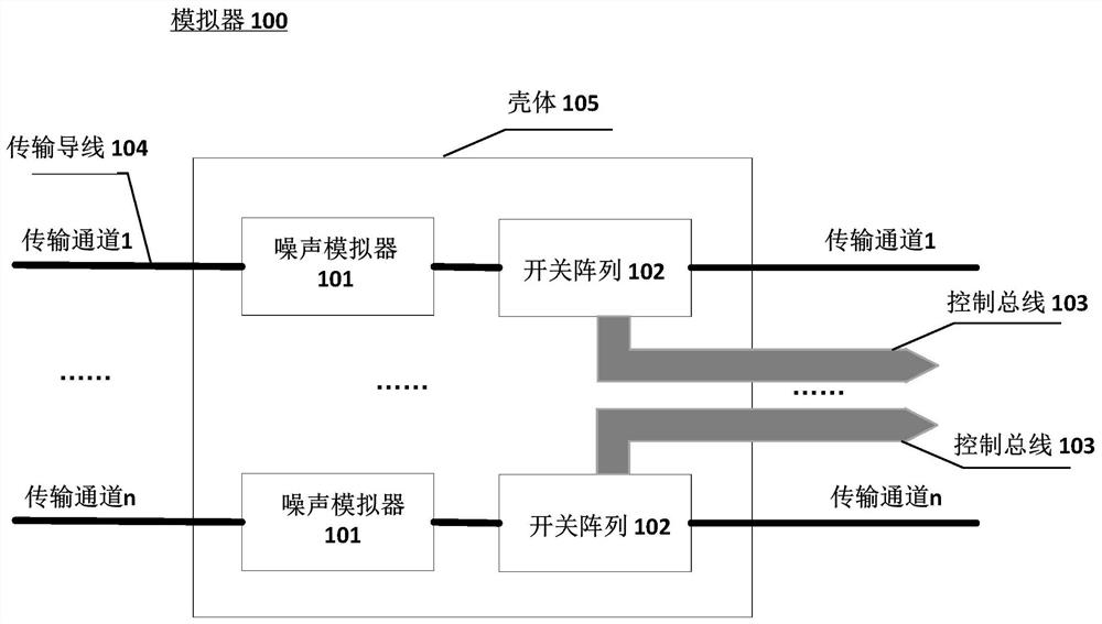
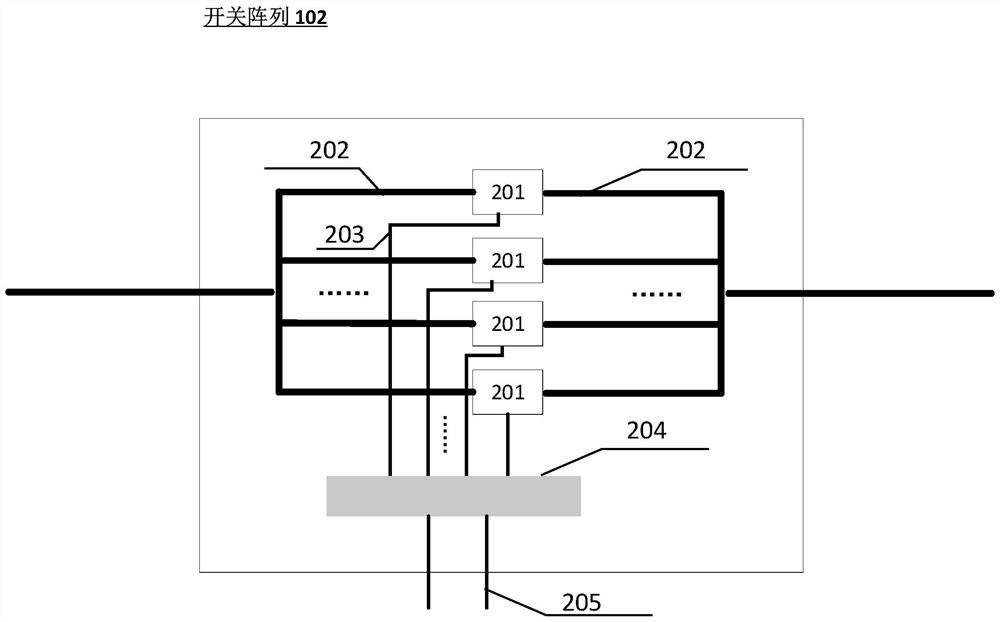
The invention relates to a simulator for simulating a conductive slip ring, which includes one or more transmission channels, wherein each transmission channel includes: a switch array, which has n switch units connected in parallel with each other, where n is an integer, each The switch unit has a conduction resistance R, and the switch array is configured to switch on and / or disconnect a corresponding number of switch units according to a control signal received from the control bus so as to adjust the resistance of the access transmission channel; the control bus is used for transmitting the control signal to the switch array; and a noise simulator configured to simulate electromagnetic interference in the conductive slip ring. Through the present invention, in addition to the transmission of electric energy and electric signals, the operating characteristics of the conductive slip ring, such as resistance change, electromagnetic noise and transient characteristics, can be more realistically simulated.

Description

technical field [0001] The invention generally relates to the field of precision machinery manufacturing, in particular to a simulator for simulating a conductive slip ring. Furthermore, the invention also relates to a method for simulating a conductive slip ring. Background technique [0002] Conductive slip rings are used to mechanically and electrically connect two relatively rotating rotating bodies, and transmit electrical energy and signals between the two rotating bodies. Precision conductive slip rings are high-tech products used to transmit electrical energy and electrical signals for relatively rotating mechanisms. They have been used in cutting-edge military fields and are key components of various precision turntables, centrifuges and inertial navigation equipment. With the improvement of the manufacturing process, such products are increasingly used in the civilian field, such as in the control of industrial automatic systems. Widely used in security, factory ...

Claims


Application Information

Patent Timeline
Patent Type & Authority Patents(China)
IPC IPC(8): H04B17/00
CPCH04B17/0087H01R39/08
Inventor 李立朱野刘会杰梁旭文程睿刘磊潘小彤刘兴富王硕
Owner SHANGHAI ENG CENT FOR MICROSATELLITES
Learn More