Cooking utensil for steam heating and steam cooker

A technology of cooking utensils and steam, which is applied in the direction of steam cooking utensils, cooking utensil lids, cooking utensils, etc. It can solve the problems of poor heating effect, uneven heating of rice, affecting the taste of rice, etc., and achieve the effect of increasing thermal efficiency and improving cooking effect

Active Publication Date: 2019-07-26
JOYOUNG CO LTD
View PDF15 Cites 0 Cited by
  • Summary
  • Abstract
  • Description
  • Claims
  • Application Information

AI Technical Summary

Problems solved by technology

The heated parts of the above heating method are concentrated in the contact position between the inner pot and the rice, so that the rice in different areas of the pot is heated unevenly during heating, the bottom is heated more than the top, and the periphery of the inner pot is heated more than the center of the inner pot, which ultimately affects the taste of rice
In the prior art, there is a structure in which steam is introduced into the rice cooker, but its heating effect is poor, and it is mostly used for moisturizing and heat preservation after the rice is cooked, and it is difficult to use only steam for cooking

Method used


Image

  • Cooking utensil for steam heating and steam cooker
  • Cooking utensil for steam heating and steam cooker
  • Cooking utensil for steam heating and steam cooker

Examples


Embodiment 1

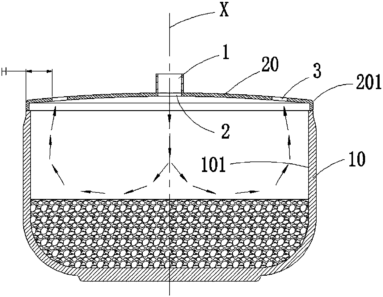
[0030] See Figure 1 to Figure 2 , which is a diagram of Embodiment 1 of a cooking appliance for steam heating according to the present invention.

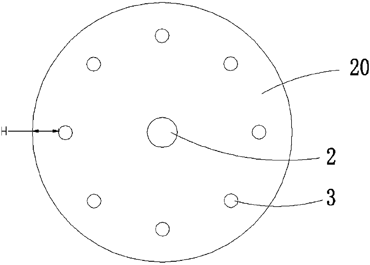
[0031] A cooking utensil for steam heating, comprising a pot body 10 and a pot cover 20 covering the pot body 10, the pot cover 20 is provided with an air inlet channel 1 leading into the pot body 10 from above the pot body 10 And the steam inlet 2 that communicates with the air inlet channel 1, and the steam outlet 3, the steam outlet 3 is located at the position near the edge 201 of the pot cover and is far away from the steam inlet 2, and then refer to figure 2 As shown, there are multiple steam outlets 3 , and each steam outlet 3 is arranged around the steam inlet 2 .

[0032] The pot body 10 is filled with food, and steam is provided to the pot body 10 through the air inlet channel 1, and then the steam enters the pot body 10 from the steam inlet port 2 to realize steam heating, and the excess steam is discharged from the s...

Embodiment 2

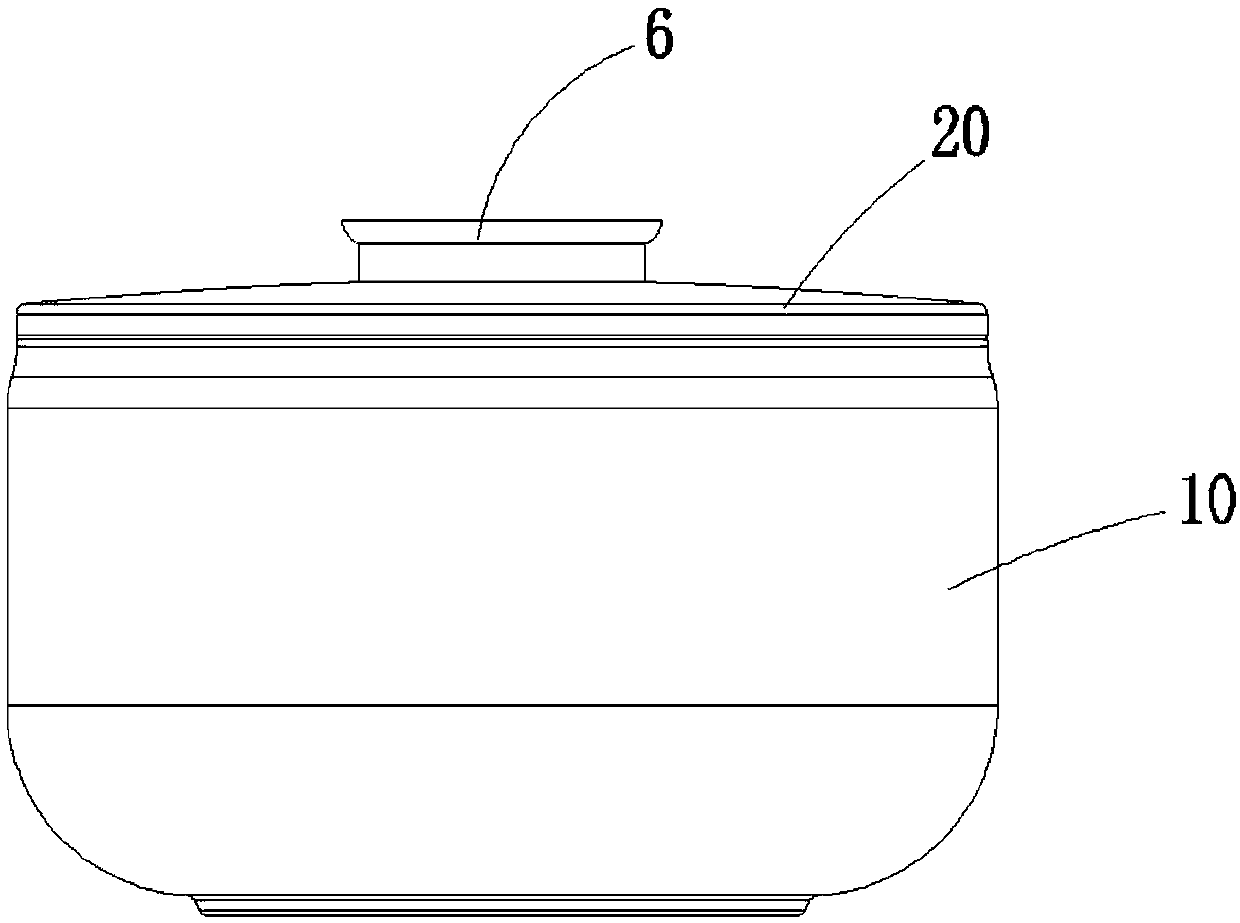
[0043] see Figure 3-4 , which is a diagram of Embodiment 2 of a cooking appliance for steam heating in the present invention. The difference from Embodiment 1 is that a unified air outlet channel 4 is also provided, as follows.

[0044] refer to Figure 4 As shown, the pot cover 20 is provided with an air outlet channel 4 , and an internal channel 5 that communicates the air outlet channel 4 with each of the steam outlets 3 is arranged in the pot cover 20 . The steam discharged from each steam outlet 3 is gathered through the unified air outlet channel 4 and then discharged together to avoid direct discharge of steam from the position of each steam outlet 3, and the steam is exported to a designated position through the outlet channel 4.

[0045] For example, the air outlet channel 4 can discharge the steam from a position that does not affect the user, such as concentrated discharge upward, or discharge toward the rear, so as to prevent the steam from being discharged from...


PUM

PropertyMeasurementUnit
Thicknessaaaaaaaaaa

Abstract

The invention provides a cooking utensil for steam heating and a steam cooker. The cooking utensil comprises a pot body and a pot cover with which the pot body is covered, and the cooking utensil is characterized in that the pot cover is provided with a steam inlet channel, a steam inlet and steam outlets, wherein steam is introduced into the pot body from the upper side of the pot body through the steam inlet channel, the steam inlet is communicated with the steam inlet channel, the steam outlets are formed in the position close to the edge of the pot cover but away from the steam inlet, andthe steam outlets are around the steam inlet. By means of the cooking utensil, introduction and discharging of steam are achieved, food is directly heated by means of the steam and cooked, and the cooking effect is good.

Description

technical field [0001] The invention relates to the technical field of kitchen appliances, in particular to a cooking appliance for steam heating and a steam rice cooker. Background technique [0002] Existing rice cookers realize the functions of cooking rice and porridge. Generally, external heating of the inner container is adopted, such as heating at the bottom (heating plate, electromagnetic heating) or heating around (IH electromagnetic heating), and the inner container absorbs heat and transfers it to the water inside. and rice until the rice is cooked. The heated parts of the above-mentioned heating method are concentrated in the contact position between the inner pot and the rice, so that the rice in different areas in the inner pot is heated unevenly during heating. In the prior art, there is a structure in which steam is passed into the rice cooker, but its heating effect is poor, and it is mostly used for moisturizing and heat preservation after the rice is cook...

Claims


Application Information

Patent Timeline
IPC IPC(8): A47J27/04A47J36/06A47J36/38
CPCA47J27/04A47J36/06A47J36/38A47J2027/043
Inventor 朱泽春王园建程凌军
Owner JOYOUNG CO LTD
Why Eureka
Try Eureka