Eureka AIR delivers breakthrough ideas for toughest innovation challenges, trusted by R&D personnel around the world.

Vibration screen

A vibrating screen and vibrating motor technology, which is applied in the direction of filter screen, solid separation, grid, etc., can solve the problems of damaged soft connection sleeve, powder leakage, soft connection damage, etc., so as to save material cost, reduce space occupation, The effect of preventing loosening

Pending Publication Date: 2019-07-26
钟祥市宇峰振动机械制造有限公司
View PDF0 Cites 0 Cited by
  • Summary
  • Abstract
  • Description
  • Claims
  • Application Information

AI Technical Summary

Problems solved by technology

In this flexible connection structure, the discharge pipe must be inserted downwards into the feed pipe to a certain height, such as about 100mm, otherwise various problems will occur: for example, when the lower end of the discharge pipe is located at the upper end of the feed pipe, if the flexible connection sleeve If it is too short, it will cause the flexible connecting sleeve to bear cyclic tension, which will greatly reduce its life, and the powder will swell in the gap between the receiving pipe and the flexible connecting sleeve, which will damage the flexible connecting sleeve at the same time. It may also cause powder leakage; and if the flexible connecting sleeve is too long, it will cause the flexible connecting sleeve to bend and wrinkle, causing the material to swell to the folds of the flexible connecting sleeve, thereby expanding the flexible connecting sleeve, allowing the The soft connection is damaged and the sealing effect cannot be achieved
[0008] In addition, for the inclined vibrating screen, the front end of the screen assembly must also be heightened, otherwise the screen assembly will touch the ground and cannot be pulled out after a certain length is drawn out, which requires the overall height of the vibrating screen and the height of the workshop floor. Increase accordingly
[0009] Therefore, the vibrating screen in the prior art is a long-standing drawback in the industry due to its unreasonable structure and dismounting methods.

Method used


Image

  • Vibration screen
  • Vibration screen
  • Vibration screen

Examples


Embodiment Construction

[0045] The technical solutions of the present invention will be clearly and completely described below in conjunction with the accompanying drawings. In the description of the present invention, it should be noted that the terms "center", "upper", "lower", "left", "right", "vertical", "horizontal", "inner", "outer" etc. The indicated orientation or positional relationship is based on the orientation or positional relationship shown in the drawings, and is only for the convenience of describing the present invention and simplifying the description, rather than indicating or implying that the referred device or element must have a specific orientation, or in a specific orientation. construction and operation, therefore, should not be construed as limiting the invention. In addition, the terms "first", "second", and "third" are used for descriptive purposes only, and should not be construed as indicating or implying relative importance.

[0046] In the description of the present i...


PUM


Abstract

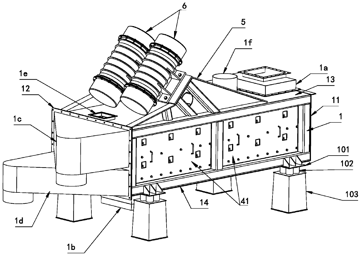
The invention discloses a screen mesh side mounted vibration screen. The vibration screen comprises a screen box, a feed port, a plurality of discharge chambers, a plurality of sets of damping springs, a vibration motor fixed seat, a vibration motor and baffles, wherein the screen box is formed by fixing a framework to a shell; a plurality of screening chambers are formed in the screen box; at least one layer of bracket is fixed to the interior of the screen box; at least one screen net assembly is arranged on each layer of bracket in a lateral drawing mode in the left-right direction; every two up-down adjacent screen chambers are separated by one layer of bracket and the corresponding at least one screen net assembly; the feed port is arranged on the screen box; the discharge chambers are arranged on the screen box and communicate with the screening chambers in a one-to-one correspondence mode; the damping springs are fixed to the bottom of the screen box; the lower ends of each setof damping springs are fixed to a lower support; the vibration motor fixed seat is fixed to the top of the screen box; the vibration motor is fixed to the vibration motor fixed seat; and the baffles are used for stopping and locking the screen net assemblies from at least one of the left side and the right side, and the baffles are detachably mounted on the screen box. The screen mesh side mountedvibration screen is convenient to disassemble and assemble, short in consumed time, small in space requirement and low in cost.

Description

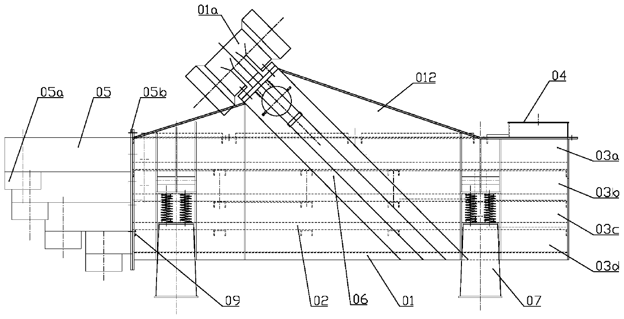
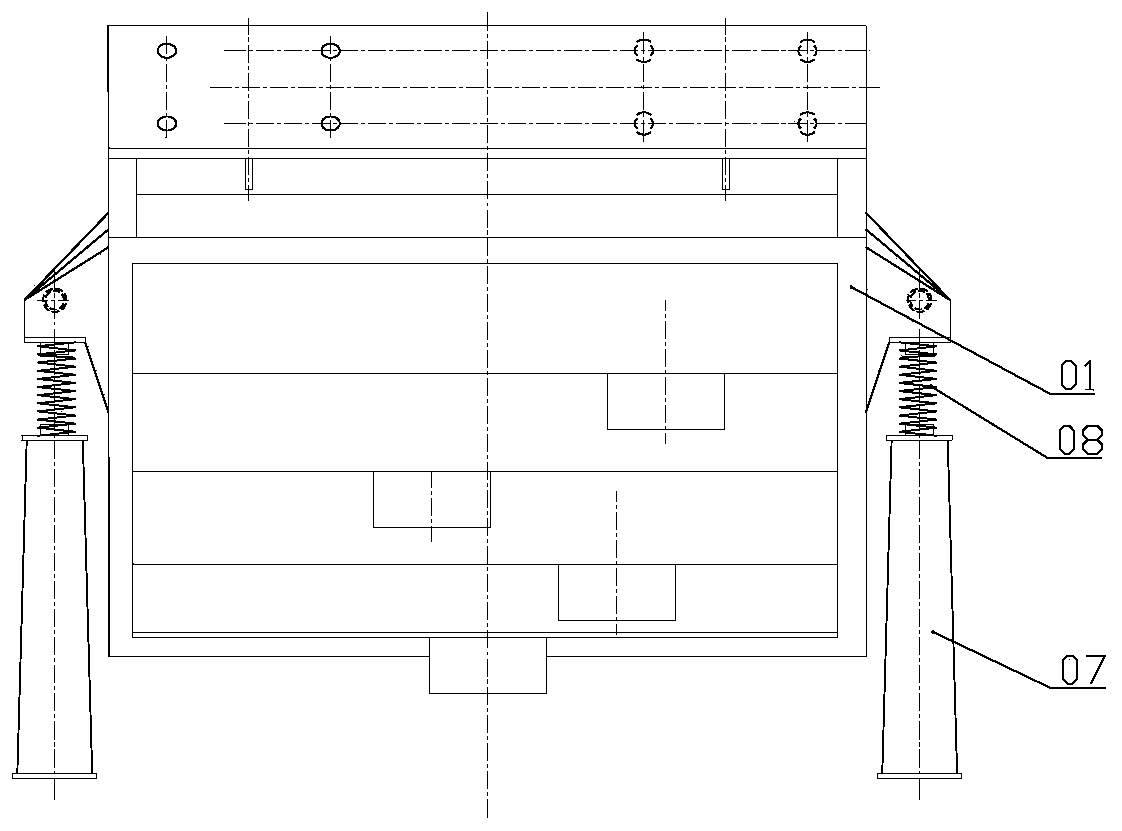
technical field [0001] The invention relates to the field of vibrating sieves, in particular to a side-mounted vibrating sieve with a screen mesh. Background technique [0002] Vibrating screens are widely used in various fields. The working intensity of the vibrating screen is high, so the screen mesh of the vibrating screen often needs to be replaced and repaired. The vibrating screen in the prior art is generally a multi-layer structure, which is roughly as figure 1 , figure 2 As shown: the inside of the screen box 01 is divided into a plurality of screen chambers 03a, 03b, 03c, and 03d arranged from top to bottom by a multi-layer screen assembly 02. The front end is fixed with a plurality of discharge bins 05, each of which extends downwards with a discharge pipe 05a, and the rear end of the discharge bins 05 forms a connecting flange 05b and is connected to the rear end of the screen box 01. A group of two damping springs are arranged at the upper and lower center ...

Claims


Application Information

Patent Timeline
IPC IPC(8): B07B1/28B07B1/46
CPCB07B1/28B07B1/4645B07B2201/04
Inventor 易家国
Owner 钟祥市宇峰振动机械制造有限公司
Why Eureka
Eureka Blog
Learn More