Gushing type circulating grain dust removing device

A dust removal device and grain technology, applied in the direction of solid separation, separating solids from solids with airflow, chemical instruments and methods, etc., can solve the problems of high pressure of hot air, inability to discharge, no dust removal, impurity removal, etc., to achieve Enhanced effect, easy to popularize and apply, simple structure effect

Inactive Publication Date: 2019-07-26
ANHUI JIESHOUSHI YUNLONG FOOD MACHINE ENG
View PDF8 Cites 4 Cited by
  • Summary
  • Abstract
  • Description
  • Claims
  • Application Information

AI Technical Summary

Problems solved by technology

The existing grain dryer does not have the function of dust removal and impurity removal. Although it has been dried for many times, the dust and impurities in it still remain in it and cannot be discharged. The grain itself will carry shells,

Method used


Image

  • Gushing type circulating grain dust removing device
  • Gushing type circulating grain dust removing device
  • Gushing type circulating grain dust removing device

Examples


Embodiment 1

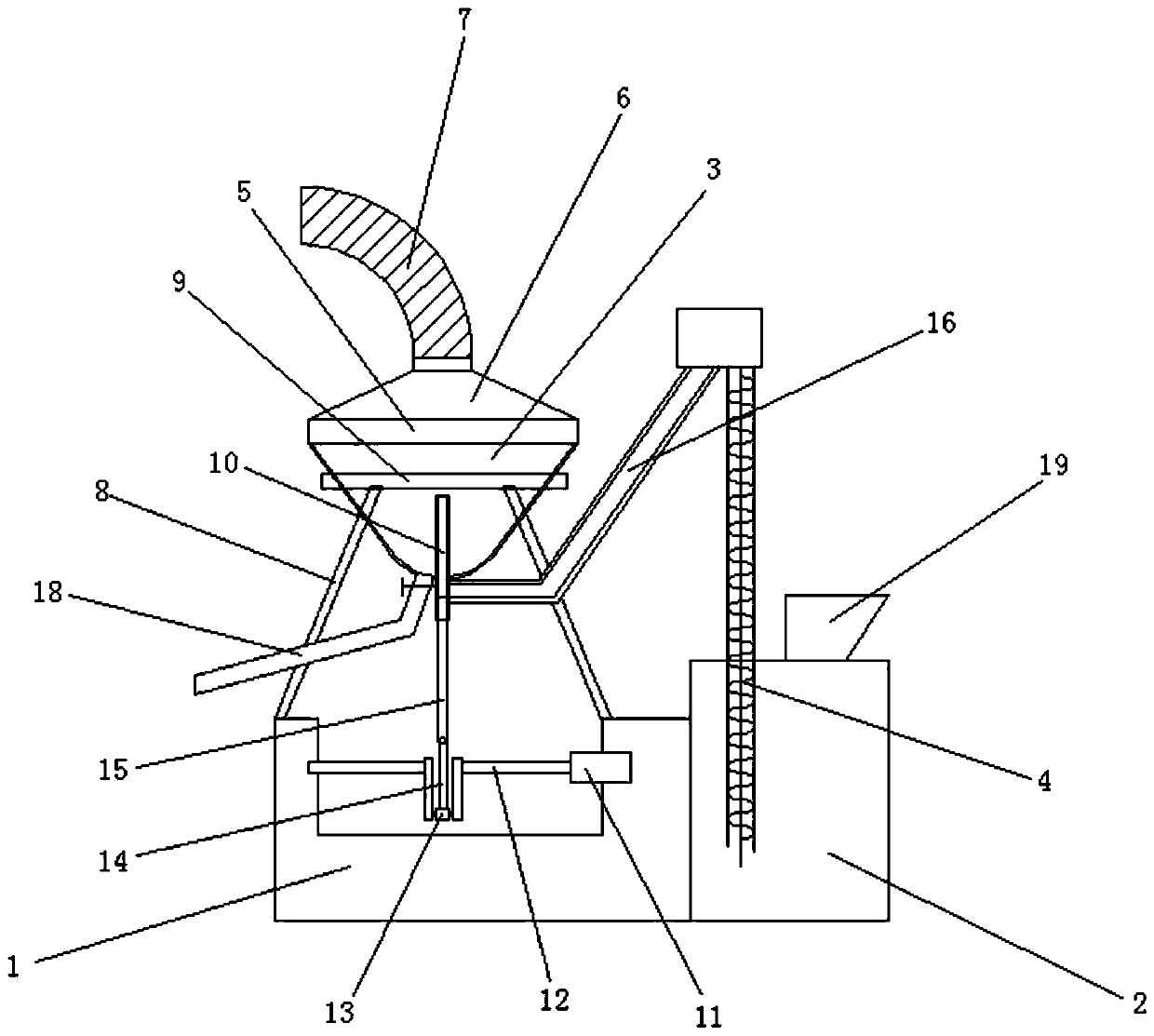
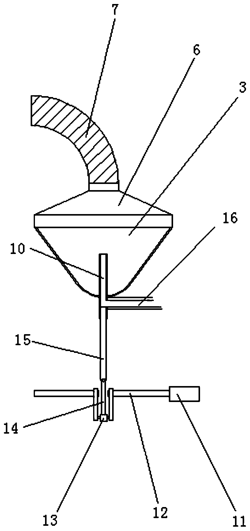
[0032] Embodiment 1: as Figure 1-4 Shown, a kind of gushing type circulation grain dedusting device comprises:

[0033] A base 1, the base 1 is set in a concave shape, a motor 11 is fixedly installed in the middle part of the inner wall on the right side of the base 1, and a crankshaft 12 is fixedly connected to the left end of the motor 11, and the left end of the crankshaft 12 is connected to the base The inner wall on the left side of the seat 1 is rotatably connected, the crankshaft 12 is rotatably sleeved with a sleeve 13, the side wall of the sleeve 13 is fixedly connected with a connecting rod 14, and the top of the connecting rod 14 is rotatably connected with a push rod 15 , the motor drives the crankshaft to rotate and drives the ejector rod to reciprocate up and down through the drum and connecting rod;

[0034] Storage bin 2, the top left side of the storage bin 2 is fixedly equipped with a hoist 4, the bottom of the hoist 4 is located at the bottom of the inner ...

Embodiment 2

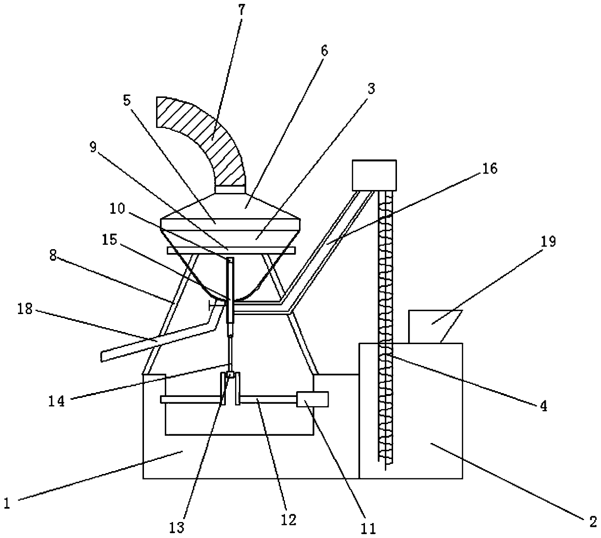
[0040] Embodiment 2: as Figure 5-7 Shown, a kind of gushing type circulation grain dedusting device comprises:

[0041] A base 1, the base 1 is set in a concave shape, a motor 11 is fixedly installed in the middle part of the inner wall on the right side of the base 1, and a crankshaft 12 is fixedly connected to the left end of the motor 11, and the left end of the crankshaft 12 is connected to the base The inner wall on the left side of the seat 1 is rotatably connected, the crankshaft 12 is rotatably sleeved with a sleeve 13, the side wall of the sleeve 13 is fixedly connected with a connecting rod 14, and the top of the connecting rod 14 is rotatably connected with a push rod 15 , the motor drives the crankshaft to rotate and drives the ejector rod to reciprocate up and down through the drum and connecting rod;

[0042]Storage bin 2, the top left side of the storage bin 2 is fixedly equipped with a hoist 4, the bottom of the hoist 4 is located at the bottom of the inner c...


PUM


Abstract

The invention relates to the field of grain processing, and discloses a gushing type circulating grain dust removing device which comprises a base. The bottom of the base is fixedly provided with a crankshaft rotating rod mechanism, the top of the base is rotatably hinged to an ejector rod, the top of the left side of a storage bin is fixedly provided with an elevator, the top of a dust removal hopper is fixedly provided with a negative pressure fan, the bottom of the dust removal hopper is fixedly connected with a grain spraying pipe, the tops of two sides of the base are provided with the dust removal hopper through supports and installation rings, a guide pipe is fixedly connected between the top of the elevator and the right side of the lower part of the grain spraying pipe, the guidepipe communicates with the grain spraying pipe, the ejector rod is movably sleeved with the bottom of the grain spraying pipe, and the left side of the bottom of the dust removal hopper is fixedly provided with a discharge pipe. The effect of controlling feeding can be achieved, grains are driven to be fluffy and uniformly distributed in the dust removal hopper in a gushing manner, dust and grainscan be separated easily, the function of circularly and repeatedly removing dust is achieved, and the dust removal effect is enhanced.

Description

[0001] Technical field: [0002] The invention relates to the field of grain processing, in particular to a gushing type circulating grain dedusting device. [0003] Background technique: [0004] Before storing grains such as rice and wheat, it is necessary to dry the grains. The usual method is to expose the grains to the sun. However, this drying method is inefficient and is easily affected by the weather and geographical environment. Many farmers expose the grains to the sun. There will also be safety hazards on the roadside, and now grain dryers are usually used instead of traditional grain drying methods. [0005] The grain dryer is mainly used for drying rice and wheat, and it can also be used for drying rapeseed and other crops after a little improvement. Grain dryer is composed of main components such as coal furnace, motor, axial flow fan and stacking rack. When the grain dryer is working, the motor drives the impeller of the axial flow fan to rotate at a high speed...

Claims


Application Information

Patent Timeline
IPC IPC(8): B07B7/01B07B11/06
CPCB07B7/01B07B11/06
Inventor 管文武曹鹏飞李洪徐旭
Owner ANHUI JIESHOUSHI YUNLONG FOOD MACHINE ENG
Why Eureka
Try Eureka