Air blowing nozzle and method of use

A blowing nozzle and air curtain technology, which is applied in metal processing equipment, welding equipment, manufacturing tools, etc., can solve the problems of single gas flow direction, inability to discharge air from the blowing nozzle, poor welding effect, etc., and achieve light volume and good blowing effect, the effect of improving welding quality

Active Publication Date: 2020-12-25
HANS LASER TECH IND GRP CO LTD
View PDF6 Cites 0 Cited by
  • Summary
  • Abstract
  • Description
  • Claims
  • Application Information

AI Technical Summary

Problems solved by technology

[0003] The technical problem to be solved by the present invention is to provide a blowing nozzle and its use method, which aims to solve the technical problem in the prior art that the gas flow direction is single, and the air in the blowing nozzle cannot be completely discharged, resulting in poor welding effect

Method used


Image

  • Air blowing nozzle and method of use
  • Air blowing nozzle and method of use
  • Air blowing nozzle and method of use

Examples


Embodiment 1

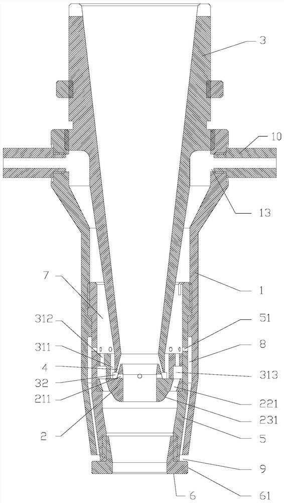
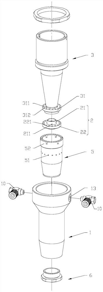
[0041] see Figure 1-4 , 6. This embodiment provides a blowing nozzle for laser welding, the blowing nozzle is used for laser welding, including: an outer tube 1, a diverter ring 2, and an inner tube 3, wherein:

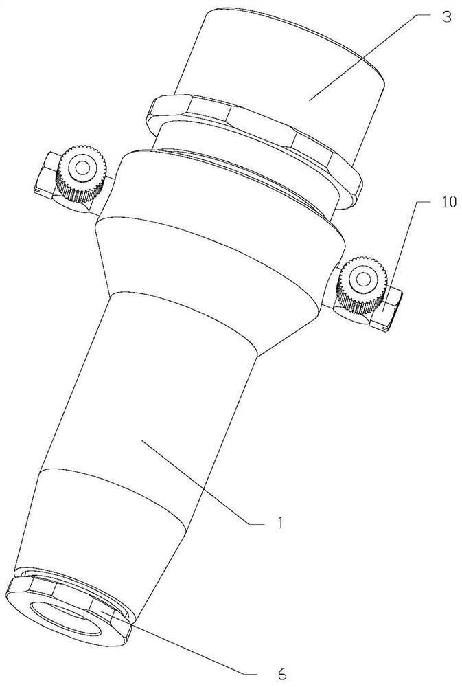
[0042] The outer pipe 1 includes an air inlet end 11 and an air outlet end 12. The wall of the outer pipe 1 is provided with an air inlet hole 13, and the air inlet hole 13 is connected with an air inlet nozzle 10, and the air inlet nozzle 10 has a function of adjusting gas pressure;

[0043] The splitter ring 2 is placed coaxially in the outer tube 1 and below the air inlet 13. The splitter ring 2 includes a first annular portion 21 and a second annular portion 22 that are coaxially arranged and have unequal outer diameters. The second annular portion The outer wall of 22 is sealed with the inner wall of the outer tube 1, and the second annular part 22 is provided with a first through hole 221 communicating with the outer tube 1;

[0044] The inner pipe 3 is used to ...

Embodiment 2

[0050] On the basis of Embodiment 1, the blowing nozzle also includes a middle pipe 5 and an air curtain ring 6. The middle pipe 5 is placed in the outer pipe 1 and is located below the air inlet 13, and the outer wall is sealed with the inner wall of the outer pipe 1. The pipe 3 extends into the middle pipe 5 and abuts against the second annular portion 22, the outer wall of the inner pipe 3 and the inner wall of the middle pipe 5 form a second space 7 communicating with the air inlet 13, and the middle pipe 5 is located on the first annular flange The pipe wall above 31 is provided with a fifth through hole 51, the splitter ring 2 is placed in the middle pipe 5, the second annular part 22 and the first annular flange 31 are fitted and sealed with the inner wall of the middle pipe 5, and the air curtain ring 6 is located at the gas outlet end 12 and sealed with the end of the middle pipe 5. The outer wall of the air curtain ring 6 is provided with a second annular flange 61, a...


PUM


Abstract

The invention provides an air-blowing nozzle and a using method. The air-blowing nozzle comprises an outer pipe, a distribution ring and an inner pipe. The inner pipe and the distribution ring are coaxially arranged in the outer pipe. A laser channel is formed in the middle of the air-blowing nozzle. Gas guided into the outer pipe is distributed into multiple paths through the distribution ring, and the multiple paths include the upper gas exhaust path passing through the upper portion of the inner pipe, the intermediate gas exhaust paths which are oppositely blown in the distribution ring andseparately flow upwards and downwards along the distribution ring, and a lower gas exhaust path flowing out of the lower portion of the outer pipe. According to the air-blowing nozzle, air in the air-blowing nozzle is completely exhausted through the upper gas exhaust path, the intermediate gas exhaust paths and the lower gas exhaust path, so that a good air-blowing effect is achieved, welding spatters are effectively reduced, the stability of the welding process is ensured, and the welding quality is improved. Meanwhile, all the components are mounted in a nested mode, so that the structureis compact, and the size is small.

Description

technical field [0001] The invention belongs to the technical field of laser welding, and in particular relates to an air blowing nozzle and a using method. Background technique [0002] Gas shielding is an important factor affecting the ideal laser welding effect. Especially in the case of high-power welding, a good blowing effect can effectively reduce welding spatter, ensure the stability of the welding process, and improve the welding quality. The shielding gas nozzle of the existing welding machine is installed on the welding head, the laser beam passes through the nozzle to perform fusion welding on the workpiece, and at the same time, the shielding gas is blown into the nozzle, and the shielding gas and the laser beam hit the surface of the workpiece together, so that the welding While protecting the welding position. However, after the shielding gas is passed into the nozzles of these existing structures, the air flow direction generated by the gas is relatively sin...

Claims


Application Information

Patent Timeline
Patent Type & Authority Patents(China)
IPC IPC(8): B23K26/14B23K26/24
CPCB23K26/1462
Inventor 邓时累陈根余唐景龙陈兵华陈焱高云峰
Owner HANS LASER TECH IND GRP CO LTD
Why Eureka
Try Eureka