A chip packaging machine

A packaging machine and chip technology, applied in the direction of packaging, transportation packaging, transportation and packaging, etc., can solve the problems of irreparable, waste of manpower and time, difficult to separate, etc., to avoid vacuum gas leakage, enhance thermal conductivity, ease The effect of being oxidized

Active Publication Date: 2020-12-11
中山家普乐电子科技有限公司
View PDF7 Cites 0 Cited by
  • Summary
  • Abstract
  • Description
  • Claims
  • Application Information

AI Technical Summary

Problems solved by technology

[0002] With the upgrading of the industrial structure of the domestic economy, the semiconductor integrated circuit industry at the top of the electronics industry has been placed high hopes and even raised to the height of the national strategy, and the chip industry is the cutting-edge product of the semiconductor industry chain, and chip packaging is undoubtedly the chip manufacturing industry. A problem that needs to be solved urgently, because the existing chip packaging operations generally have poor packaging, and the poor packaging will cause the package to fall when the product is opened, causing the pins to crooked or broken, so that they cannot be repaired and scrapped, and When several chips with the same package and different functions are packaged together, it is difficult to separate them after they are accidentally scattered and mixed together. If they are separated, a lot of manpower and time will be wasted. Most importantly, when the bare chips are scattered After that, it can no longer be used and can only be scrapped, which will inevitably cause unnecessary waste. Based on the above premise, this case developed a chip packaging machine to solve this problem

Method used


Image

  • A chip packaging machine
  • A chip packaging machine
  • A chip packaging machine

Examples


Embodiment

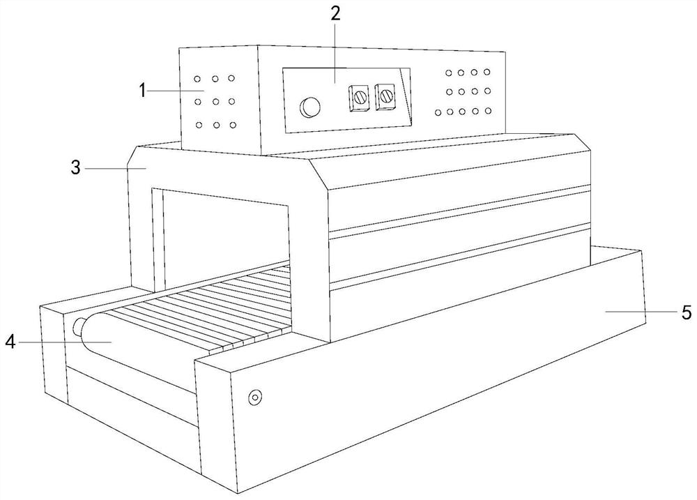
[0026] see figure 1 , the present invention provides a kind of chip packing machine, and its structure comprises: console 1, operating platform 2, pressing mechanism 3, conveying tape 4, base 5, described console 1 is provided with operating platform 2 and is connected with pressing mechanism 3 connected, the pressing mechanism 3 is connected to the conveyor belt 4, the conveyor belt 4 is set on the top of the base 5, the console 1 is mainly used to control the movement and operation of the structural components in the pressing mechanism, and the operation panel 2 is used to control the opening of the power supply The operation mode of the equipment can be selected by buttons and knobs corresponding to the function of closing and closing. The pressing mechanism 3 is mainly used to press and separate the outer packaging bags of chips to avoid mixing different types of chips. The conveying tape 4 is used for chips in The transfer structure during packaging relies on it to comple...


PUM


Abstract

The invention discloses a chip packaging machine which structurally comprises a control table, an operation screen, a pressing mechanism, a conveying rolling belt and a base. The chip packaging machine has the beneficial effects that the pressing mechanism is studied, separation devices in the mechanism are used for conducting separating packaging on chip packaging bags, synchronous classifying can be conducted on chips while packaging is conducted, and filling of vacuum gas is conducted so that it can be ensured that the chips have the good packaging performance; and the separation devices are used so that grid rubber bars in the longitudinal direction and the transverse direction can be formed, it is ensured that the chips can be classified during packaging, in addition, the best sealing performance can be ensured, vacuum gas leakage in the packaging bags is avoided, meanwhile, due to filling of the vacuum gas, oxidation of the chips can be effectively relieved, and the vacuum gas can also serve as a buffering protection layer so that the chips can be prevented from being fractured the first time the chips are impacted.

Description

technical field [0001] The invention relates to the field of chip packaging, in particular to a chip packaging machine. Background technique [0002] With the upgrading of the industrial structure of the domestic economy, the semiconductor integrated circuit industry at the top of the electronics industry has been placed high hopes and even raised to the height of the national strategy, and the chip industry is the cutting-edge product of the semiconductor industry chain, and chip packaging is undoubtedly the chip manufacturing industry. A problem that needs to be solved urgently, because the existing chip packaging operations generally have poor packaging, and the poor packaging will cause the package to fall when the product is opened, causing the pins to crooked or broken, so that they cannot be repaired and scrapped, and When several chips with the same package and different functions are packaged together, it is difficult to separate them after they are accidentally sca...

Claims


Application Information

Patent Timeline
Patent Type & Authority Patents(China)
IPC IPC(8): B65B9/04B65B51/10B65B31/04B65B61/06
CPCB65B9/045B65B31/04B65B51/10B65B61/06
Inventor 王淑琴
Owner 中山家普乐电子科技有限公司
Why Eureka
Try Eureka