Automatic four-axis cast film winding machine

A cast film and winder technology, which is applied in the direction of coiling strips, thin material processing, transportation and packaging, etc., can solve the problem of reducing the service life of the air shaft and the installation components of the air shaft, and cannot effectively improve the casting film. Rewinding speed, poor rewinding effect and other problems, to achieve the effect of saving rewinding time, reducing safety and saving working time

Active Publication Date: 2019-07-26
CHANGLONGXING SCI & TECH SHENZHEN CO LTD
View PDF10 Cites 14 Cited by
  • Summary
  • Abstract
  • Description
  • Claims
  • Application Information

AI Technical Summary

Problems solved by technology

The single winding method of the rewinding roller is easy to cause the problem that the rewinding roller rubs the cast film and causes the cast film to be damaged, while the single winding method of the air expansion shaft is easy to stretch the cast film and form ribs on the cast film surface. Poor winding effect
[0004] In the existing technology, there is still a single-threaded operation in the process of winding the cast film of the paper tube, and the paper tube needs to perform the processes of arrangement, casing, winding and unwinding in sequence, and only the internal structure of the single process is modified It is also impossible to effectively improve the winding speed of the cast film
Repeated rewinding of the air shaft in the paper tube set will also easily cause the temperature of the air shaft to rise after prolonged use, reducing the service life of the air shaft and the installation components of the air shaft

Method used


Image

  • Automatic four-axis cast film winding machine
  • Automatic four-axis cast film winding machine
  • Automatic four-axis cast film winding machine

Examples


Embodiment 1

[0085] Embodiment 1: Concrete structure and work flow of paper tube arrangement assembly 1

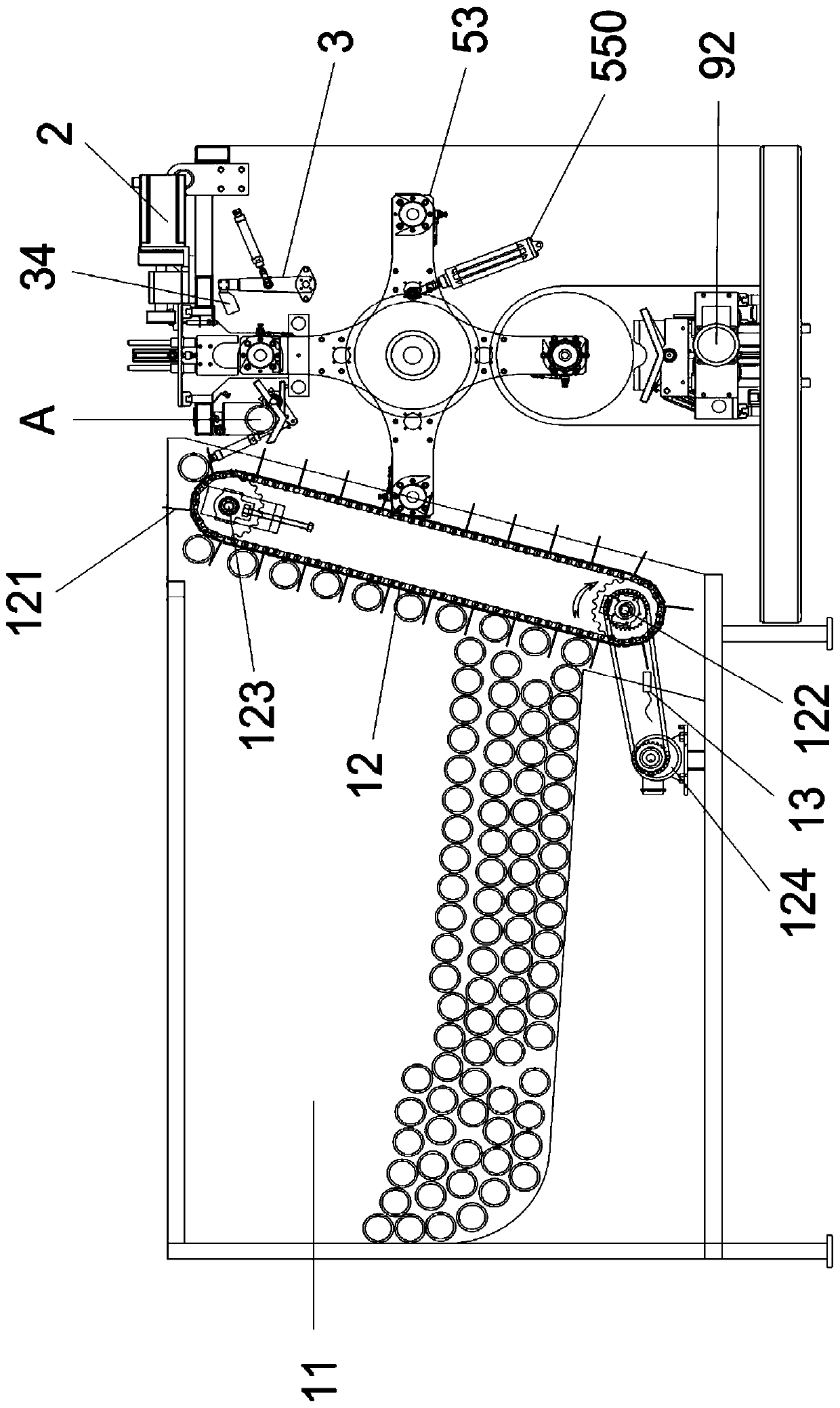
[0086] Please refer to image 3 , Figure 4 with Figure 5 , the paper tube arrangement assembly 1 includes a paper tube box 11, and the paper tube box 11 is used for storing paper tubes. One side of the paper tube box 11 is provided with a transport crawler 12 for transporting paper tubes. In order to facilitate the transport of paper tubes by the transport track 12, the bottom surface of the paper tube box 11 is inclined, and the bottom surface of the paper tube box 11 is away from the One side of the transport crawler 12 is inclined to the side close to the transport crawler 12 . A plurality of crawler spacers 121 are equidistantly arranged on the transport track 12 , and each single paper tube moves to two adjacent track spacers 121 and is transported by the transport track 12 .

[0087] Both ends of the transport crawler 12 are provided with a transport driving wheel 122 and a...

Embodiment 2

[0099]Embodiment 2: Concrete structure and work flow of the paper tube assembly 2

[0100] Please refer to Figure 4 , Image 6 , Figure 7 with Figure 8 , the paper tube assembly 2 includes a sleeve seat 21 for supporting the paper tubes. As described in Embodiment 1, when the arranged paper tubes are moved from the paper tube arrangement assembly 1 to the paper tube assembly 2 for threading When the tubes are working, the arranged paper tubes are moved from the transfer base 14 to the sleeve base 21 . A third photoelectric switch 22 is arranged on one side of the casing socket 21 . When the third photoelectric switch 22 detects that there is no paper tube on the sleeve seat 21, the third photoelectric switch 22 drives the transfer seat 14 to rotate, and the paper tube on the transfer seat 14 moves to the sleeve. on the socket 21.

[0101] A casing baffle 211 is arranged on one side of the casing seat 21, and the casing baffle 211 prevents the paper tube from rolling o...

Embodiment 3

[0112] Embodiment 3: Concrete structure and work flow of defective component 3

[0113] Please refer to figure 1 , figure 2 , image 3 , Figure 7 , Figure 8 , Figure 9 , Figure 10 The purpose of the rejected product assembly 3 is to remove the paper tube that cannot be installed on the air shaft 52 due to deformation out of the paper tube assembly 2 . And for the paper tube assembly 2, when the sleeve work is performed in the paper tube assembly 2, the push claws 24 in the paper tube assembly 2 mainly push the paper tube to perform the sleeve. When the paper tube cannot be sleeved on the air expansion shaft 52, the push claw 24 will be pushed by the paper tube. Therefore, the paper threading tube assembly 2 is also provided with a protection cylinder 27 and a travel switch 28 installed between the push claw 24 and the clamping cylinder 26 . The protection cylinder 27 prevents the paper tube pushing claws 24 from damaging the components in the paper tube assembly 2...


PUM


Abstract

The invention provides an automatic four-axis cast film winding machine. The automatic four-axis cast film winding machine is provided with a plurality of expansion shafts, the expansion shafts at different positions can carry out tube sleeving, cast film winding, roll moving-out and standing for cooling down correspondingly, the expansion shafts are driven by a motor to change positions to realize function switching of the plurality of expansion shafts, so that not only the tube sleeving, cast film winding and roll moving-out processes of the expansion shafts can be separated to be independent to save the cast film winding time, but also the expansion shafts can be left to stand for cooling down after working so as to prolong the service lives of the expansion shafts and an expansion shaft installation assembly; and in the meanwhile, a paper tube conveying assembly and a paper tube sleeving assembly are independent from an expansion shaft winding structure, so that paper tubes can bearranged and subjected to tube sleeving while cast films are wound around the expansion shafts, and the winding working time is shortened. A defective product returning assembly of the winding machinecan move damaged paper tubes which cannot sleeve the expansion shafts out of the internal structure of a winding machine body, so that the internal structure of the machine body is stabilized and thestability and safety of the cast film winding process are ensured.

Description

technical field [0001] The invention relates to the technical field of cast film machines, in particular to a four-axis automatic cast film winder. Background technique [0002] During the transportation and storage of the paper tube, it is inevitable that the paper tube cannot be installed on the inflatable shaft due to damage and deformation. If the deformed paper tube is forcibly installed on the air shaft, it may not only cause damage to the structure of the paper tube or the air shaft due to pressure, but also affect the winding of the cast film or the quality of the finished product during the winding process of the cast film. It is also easy to produce safety accidents when the paper tube is off the shaft. [0003] At the same time, the current casting film winding method often adopts a single rotation winding of a winding roller or an air expansion shaft. The single winding method of the rewinding roller is easy to cause the problem that the rewinding roller rubs t...

Claims


Application Information

Patent Timeline
Patent Type & Authority Applications(China)
IPC IPC(8): B65H75/24B65H18/00B65H18/10B65H19/30
CPCB65H18/00B65H18/10B65H19/30B65H75/243B65H2301/417B65H2701/1133B65H2701/1752
Inventor 徐惠良胡超飞
Owner CHANGLONGXING SCI & TECH SHENZHEN CO LTD
Why Eureka
Try Eureka