Prestress gradient section UHPC beam bridge

A prestressed, gradient technology, applied in the direction of bridges, bridge parts, bridge materials, etc., can solve the problems of affecting structural quality, prefabricated bridge deck drop angle defects, steel collision and fracture, etc., to avoid potential safety hazards, size reduction, reduction high effect

Pending Publication Date: 2019-07-26
江苏东南结构防灾工程有限公司
View PDF0 Cites 1 Cited by
  • Summary
  • Abstract
  • Description
  • Claims
  • Application Information

AI Technical Summary

Problems solved by technology

[0002] Beam bridges are bridges with girders as the main load-bearing components. At present, in bridge construction, the prefabricated bridge decks of beam bridges usually adopt the structural form of I-beams, π-shaped beams or slab girders. The reinforced concrete structure has unavoidable shortcomings such as heavy structural weight (self-heavy), unfavorable transportation, and difficult hoisting.
In addition, during on-site construction, the prefabricated bridge decks need to be connected as a whole through cast-in-place wet joints. The usual practice is that the upper and lower layers of the bridge deck are installed at the end of the prefabricated bridge deck. Extend out to a certain length, and the upper and lower steel bars of the outhanging part can be made into an integral closed type. In order to ensure the reliability of the connection force of the cast-in-place wet joint, generally the outstretching steel bars of adjacent bridge decks need to be close to each other and welded Together (in fact, there are as many as 200 or more unilaterally protruding steel bars on an ordinary beam—), so many steel bars need to be positioned successfully, which puts high requirements on the accuracy of hoisting of large-scale structures, and hoisting often occurs During the process, the steel bars collide with each other and break, and even the prefabricated bridge deck is damaged by the corners and defects after being hit by the steel bars, which affects the structural quality. In addition, a large amount of labor costs for welding workers are required on site, so the construction period on site is relatively long

Method used


Image

  • Prestress gradient section UHPC beam bridge
  • Prestress gradient section UHPC beam bridge

Examples


Embodiment

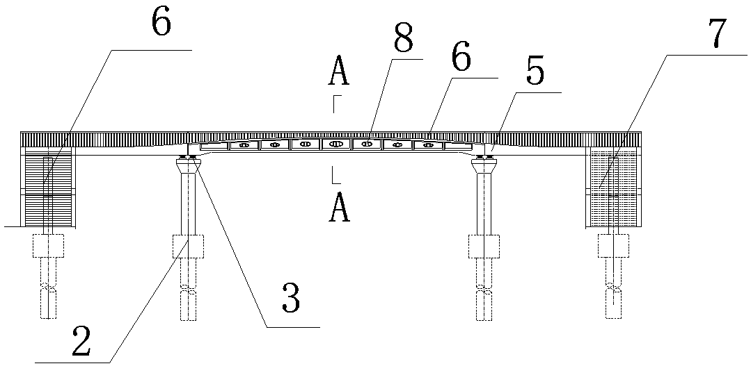
[0019] This embodiment takes a pedestrian bridge in a certain city as an example for illustration. Since the bridge is located in the central area of ​​the city, in order to reduce the impact on urban traffic, the construction method of prefabricating the bridge in the factory and overall hoisting and installation on site is adopted.

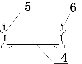
[0020] Such as figure 1 and figure 2 As shown, the prestressed gradient cross-section UHPC girder bridge of the present embodiment is used as the middle girder bridge of the flyover, including a superstructure 1, a substructure 2, and a support 3 arranged between the superstructure 1 and the substructure 2; the superstructure 1 is composed of a bottom plate 4 and webs 5 located on both sides of the bottom plate 4. The upper structure 1 is an integrated structure with a U-shaped cross section and is prefabricated by UHPC. The web 1 is provided with prestressed pipes ( not shown in the figure). The middle girder bridge both sides of overpass ar...


PUM


Abstract

The invention relates to a prestress gradient section UHPC beam bridge, including anupper structure, a lower structure, and a supporting seat arranged between the upper structure and the lower structure. The upper structure is composed of a baseplate and webs arranged on both sides of the baseplate. The upper structure is of an integral structure with a U-shaped cross section and is prefabricatedfromUHPC. Prestress pipelines are arranged on the webs. Different froma traditional beam bridge structurewhich usesabaseplate as a bearing member, a main beam of the prestress gradient section UHPC beam bridge adopts a U-shaped beam, the websare placed above a bridge deck,and the vertical websare taken as bearing members, so that the building height of the baseplate is greatly reduced, lightweightis achieved, and prefabrication, transportation and lifting are convenient.

Description

technical field [0001] The invention relates to a UHPC girder bridge with prestressed gradient cross section, which belongs to the technical field of bridge construction. Background technique [0002] Beam bridges are bridges with girders as the main load-bearing components. At present, in bridge construction, the prefabricated bridge decks of beam bridges usually adopt the structural form of I-beams, π-shaped beams or slab girders. The reinforced concrete structure has unavoidable shortcomings such as heavy structural weight (self-heavy), unfavorable transportation, and difficult hoisting. In addition, during on-site construction, the prefabricated bridge decks need to be connected as a whole through cast-in-place wet joints. The usual practice is that the upper and lower layers of the bridge deck are installed at the end of the prefabricated bridge deck. Extend out to a certain length, and the upper and lower steel bars of the outhanging part can be made into an integral ...

Claims


Application Information

Patent Timeline
IPC IPC(8): E01D1/00E01D19/00E01D101/28
CPCE01D1/00E01D19/00E01D2101/28
Inventor 夏瑾
Owner 江苏东南结构防灾工程有限公司
Why Eureka
Try Eureka