Forming method of composite foundation pile and grouting member of composite foundation pile

A forming method and composite foundation technology, which can be used in foundation structure engineering, sheet pile walls, buildings, etc., can solve the problems of reduced bearing capacity of composite foundation piles, small shrinkage and expansion rates of prefabricated piles, hidden dangers of engineering quality and safety, etc. The effect of ensuring reliable contact and eliminating hidden dangers of engineering quality

Inactive Publication Date: 2019-07-26
周兆弟
View PDF0 Cites 4 Cited by
  • Summary
  • Abstract
  • Description
  • Claims
  • Application Information

AI Technical Summary

Problems solved by technology

[0003] However, this kind of composite foundation pile has the following technical problems: after the construction is completed, the soil pile formed by mixing cement and soil will gradually condense, and the soil pile will shrink significantly during the condensing process, while the prefabricated pile will not shrink due to its own strength. Higher, and prefabrication has been completed in the factory, so the shrinkage rate and expansion rate of the prefabricated piles are very small, basically negligible, which makes the separation between the soil piles and the prefabricated piles that are originally close together
[0004] As we all know, most of the bearing capacity of the pile itself comes from the friction between the pile body and the surrounding matrix, especially the pull-out resistance of the pile, which is more dependent on the friction between the pile body and the surrounding matrix. After the prefabricated piles are separated, the bearing capacity of the composite foundation piles will be greatly reduced, which will cause serious safety hazards to the quality of the project

Method used


Image

  • Forming method of composite foundation pile and grouting member of composite foundation pile
  • Forming method of composite foundation pile and grouting member of composite foundation pile
  • Forming method of composite foundation pile and grouting member of composite foundation pile

Examples


no. 1 example

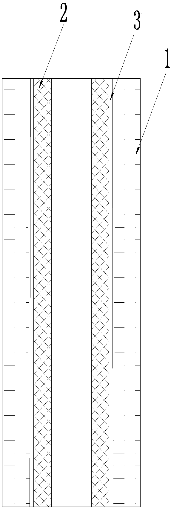
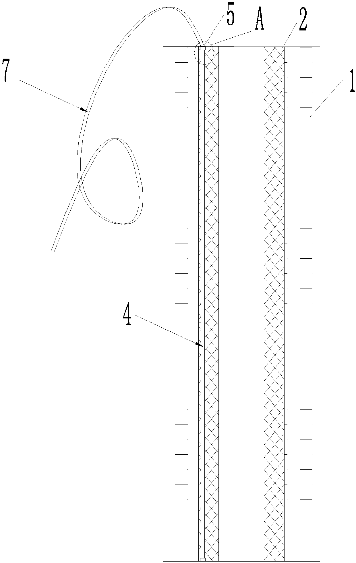
[0075] The first embodiment: Please first refer to Figure 2 to Figure 7. In the first embodiment, the grouting components include the prefabricated pile 2 located in the foundation and the cement-soil solidification layer covering the periphery of the prefabricated pile 2. The cement-soil solidification layer is formed by mixing cement and soil, and the prefabricated pile 2 A grouting pipe 4 is also arranged on the top, and the grouting pipe 4 is used for pouring cement slurry into the gap between the cement-soil solidified layer and the outer surface of the prefabricated pile 2, and the external pipeline 7 is used for connecting with the pulping machine.

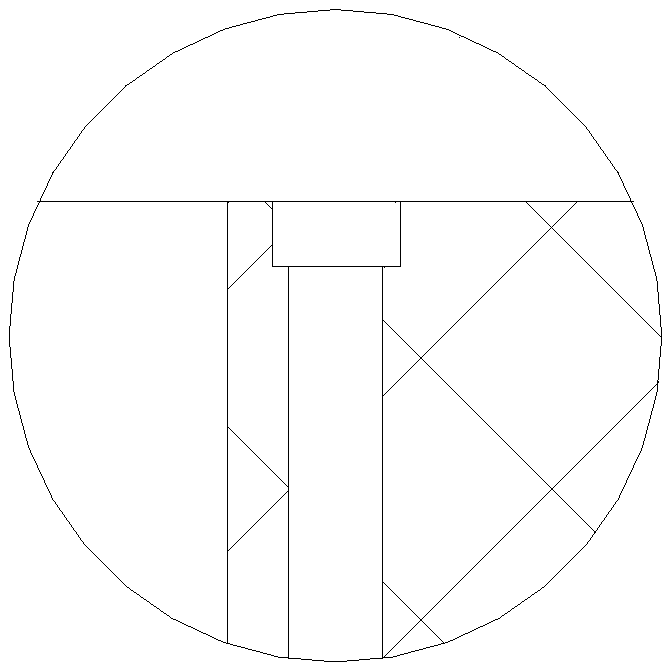
[0076] The prefabricated pile 2 is a hollow pile, and the grouting pipe 4 is pre-embedded in the prefabricated pile 2. In order to realize the connection of the grouting pipes 4 in two adjacent sections of the prefabricated pile 2, a connecting cavity 5 is provided on the top of the prefabricated pile 2. Such as figure 2...

no. 2 example

[0077] The second embodiment: please refer to Figure 8 to Figure 11. The difference from the first embodiment is that the grouting pipe 4 in this embodiment is located on the outer surface of the prefabricated pile 2, so the grouting pipe 4 can be set at the construction site, and the pipe buckle 8 can be used to fasten the grouting pipe 4 at the construction site. The grouting pipe 4 is fixedly arranged on the outer surface of the prefabricated pile 2, and the grouting pipe 4 is lowered into the cement soil together with the prefabricated pile 2, and the external pipeline 7 is used for connecting with the pulping machine.

[0078] In the second embodiment, the prefabricated pile 2 is a hollow pile, such as Figure 9 to Figure 11. The cross-section of the hollow pile can be circular, rectangular or regular hexagonal. Of course, the cross-sectional shape of the hollow pile can also be other shapes. The specific shape of the cross-section of the hollow pile has no effect on the...

no. 3 example

[0079] The third embodiment: please refer to Figure 12 to Figure 15. The difference from the second embodiment is that the grouting pipe 4 in this embodiment specifically includes a grouting main pipe 41 and a grouting branch pipe 42, wherein the grouting branch pipe 42 is pre-embedded in the prefabricated pile 2 and distributed along the lateral direction, One end of the grouting branch pipe 42 leads to the outer surface of the prefabricated pile 2 , the grouting main pipe 41 is vertically arranged, and the grouting main pipe 41 communicates with the other end of the grouting branch pipe 42 . The prefabricated pile 2 in this embodiment is also a hollow pile, and the grouting main pipe 41 is arranged in the middle hole of the prefabricated pile 2, as Figure 12 As shown, the grouting main pipe 41 can also be set in the middle hole of the prefabricated pile 2 at the construction site through the pipeline buckle 8, and then it is lowered into the cement soil together with the p...


PUM


Abstract

The invention relates to a forming method of a composite foundation pile. The forming method comprises the steps that (1) the position of the foundation pile is selected; (2) a soil body is mixed withcement slurry to form cement soil by a method of spraying the cement slurry and stirring while drilling or a method of spraying the cement slurry and stirring after the completion of drilling at theselected position; (3) a precast pile is lowered into the cement soil; and (4) after predetermined curing time, the cement slurry is injected again into a gap between the outer surface of the precastpile and the cement soil. The forming method enables a shrinkage joint generated due to shrinkage in the solidification process of the cement soil to be filled, ensures reliable contact between the cement soil and the precast pile, or enables the cement soil to be in reliable contact with the precast pile through the subsequently poured cement slurry, thereby ensuring that the composite foundationpile has sufficient bearing capacity and pull-out resistance, and eliminating the engineering quality hidden danger caused by the shrinkage joint. The invention further relates to a grouting member of the composite foundation pile.

Description

technical field [0001] The invention relates to the technical field of civil engineering, in particular to a forming method of a composite foundation pile and a grouting component of the composite foundation pile. Background technique [0002] Deep-stirring cement-soil pile is an effective form of soft foundation treatment at present. It uses cement as the main agent of curing agent, and uses a mixing pile machine to spray cement into the soil and then fully mixes with the soil. A series of physical and chemical reactions harden the soft soil. In order to further enhance the bearing capacity of the deep-mixed cement-soil pile, a composite foundation pile has also appeared. Putting it into the pile hole of the mixture of soil and cement, after the mixture is solidified, the periphery of the prefabricated pile and the consolidation layer formed by wrapping the cement and the bottom of the pile after mixing with the soil, the bearing capacity of this kind of composite pile foun...

Claims


Application Information

Patent Timeline
Patent Type & Authority Applications(China)
IPC IPC(8): E02D5/50E02D5/24E02D5/30E02D15/04E02D5/62
CPCE02D5/24E02D5/30E02D5/50E02D5/62E02D15/04
Inventor 周兆弟
Owner 周兆弟
Why Eureka
Try Eureka