Leakage-free hydraulic buffering vacuum breaker valve

A technology of hydraulic buffering and vacuum destruction, which is applied in the directions of safety valves, balance valves, valve devices, etc., can solve the problems of the failure of the buffering function of the air supply device, the hidden danger of the operation of the turbine, the metal collision between the valve plate and the valve seat, etc., and achieves a simple structure. , Axial force balance, the effect of avoiding seal wear and leakage

Pending Publication Date: 2019-07-26
秦皇岛森润滋科技有限公司
View PDF0 Cites 4 Cited by
  • Summary
  • Abstract
  • Description
  • Claims
  • Application Information

AI Technical Summary

Problems solved by technology

[0003] Since the valve stem and the valve plate are connected and move together, the matching part between the bottom of the hydraulic cylinder and the valve stem must be equipped with a movable seal. After a period of operation, the seal will inevitably wear out, and the hydraulic oil in the hydraulic cylinder will gradually leak outside. When the hydraulic oil in the hydraulic cylinder After all leaks, the cushioning function of the air supply device will fail, and when the work continues, the valve plate and the valve seat will have a strong metal impact, which will not only generate strong noise, but also accelerate the damage of components, and at the same time bring safety hazards to the operation of the turbine

Method used


Image

  • Leakage-free hydraulic buffering vacuum breaker valve
  • Leakage-free hydraulic buffering vacuum breaker valve
  • Leakage-free hydraulic buffering vacuum breaker valve

Examples


Embodiment

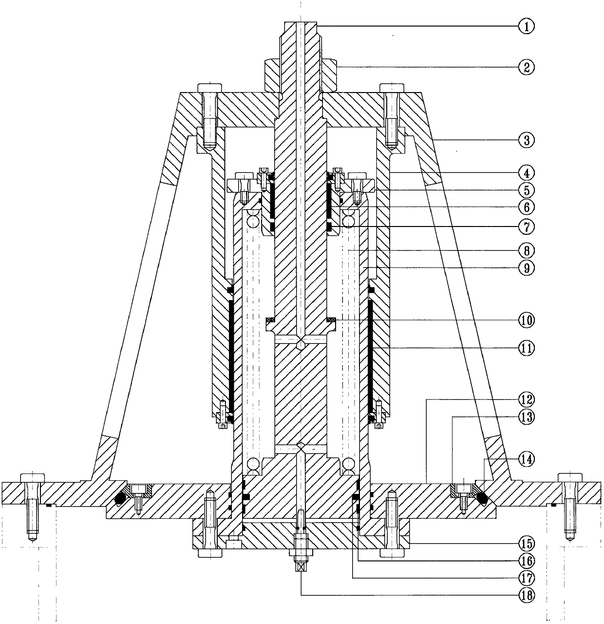
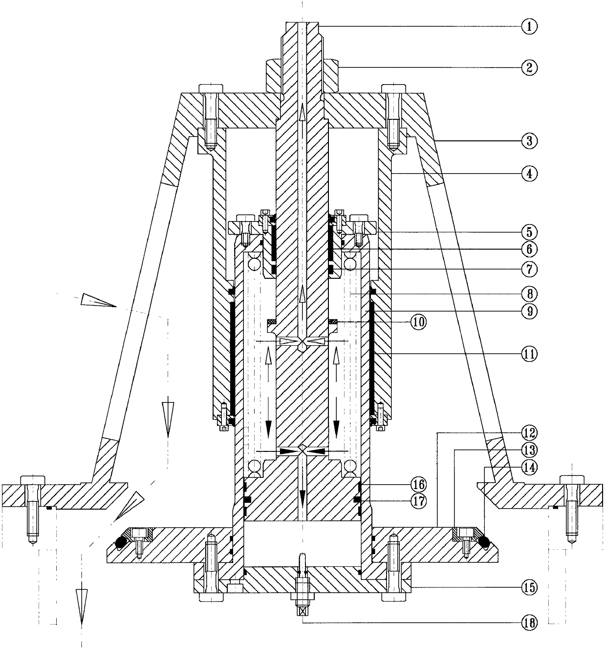
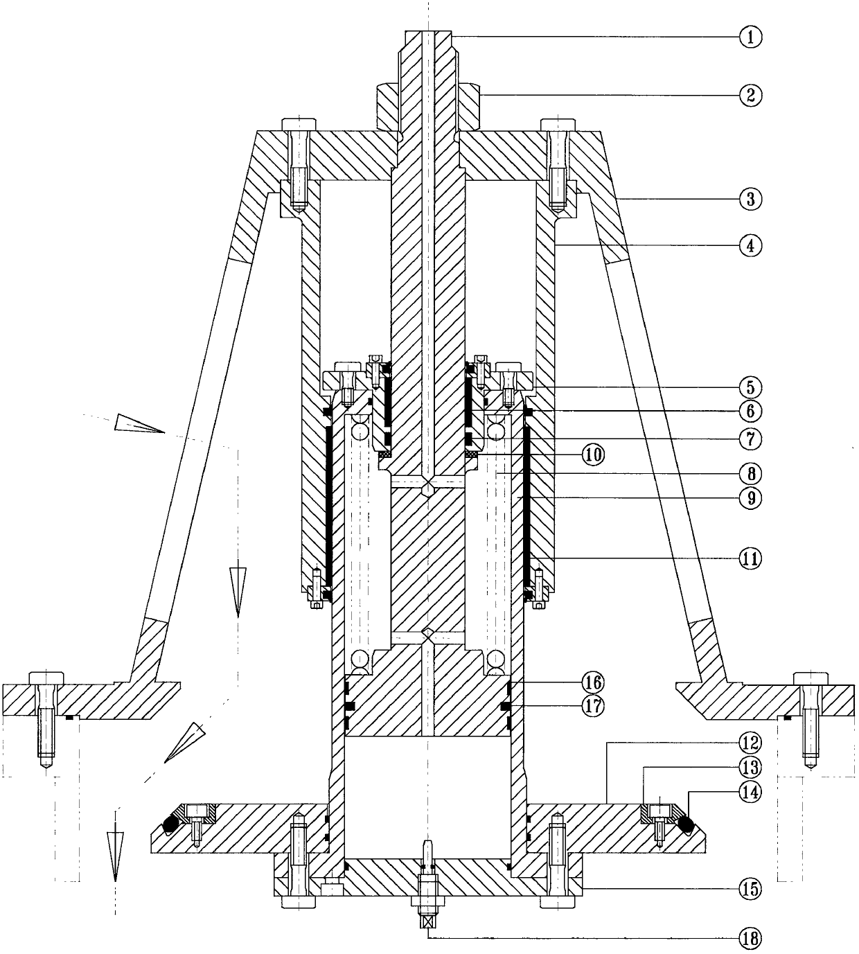
[0024] Such as Figure 1-Figure 4 As shown, a non-leakage hydraulic buffer vacuum breaks the gas supply valve, which consists of a valve stem 1, a nut 2, a valve body 3, a support sleeve 4, an upper cylinder head 5, a valve stem bearing bush 6, a valve stem seal 7, a spring (8 ), hydraulic cylinder 9, buffer plate 10, valve plate 12, pressure plate 13, main seal 14, lower cylinder cover 15, guide belt 16, piston seal 17, and throttle valve 18.

[0025] Such as Figure 1-Figure 4 As shown, the upper end of the valve stem 1 is provided with intake and exhaust holes, the bottom end of the valve stem 1 is provided with an oil hole, the middle part of the valve stem 1 is provided with a boss, the boss is provided with a buffer plate 10, and the valve stem 1 is provided with a ventilation passage, oil passage, the valve stem 1 is fixedly connected with the valve body 3 through the nut 2, the lower end of the valve stem 1 and the spring 8 are put into the hydraulic cylinder 9, and t...


PUM


Abstract

The invention provides a leakage-free hydraulic buffering vacuum breaker valve. According to the vacuum breaker valve, a hydraulic cylinder and the valve plate are arranged, wherein the hydraulic cylinder is installed on the valve plate and acts together with the valve plate, a sliding seal between the bottom of the hydraulic cylinder and a valve rod is located inside a hydraulic buffering cavity,so that complete sealing in the hydraulic cylinder is guaranteed, hydraulic buffer oil is in a completely sealed state, sealing abrasion leakage is avoided, and the service life of the vacuum breakervalve is prolonged; moreover, a throttling valve is arranged, the buffering effect of the valve plate in the closing position is improved, noise generated through collision of the valve plate and a valve seat is reduced, a supporting sleeve plays a role in supporting the hydraulic cylinder, and further balances radial force of opening and closing of the valve plate so as to prolong the fatigue life of the vacuum breaker valve, meanwhile, a spring is arranged, so that axial force is balanced; and in addition, the vacuum breaker valve is simple in structure, reasonable in design, safe and reliable, and potential safety hazards during operation of a water turbine are effectively reduced.

Description

technical field [0001] The invention provides a non-leakage hydraulic buffer vacuum breaking air supply valve, which belongs to the technical field of water turbine equipment. Background technique [0002] At present, the air supply device installed in the turbine often adopts hydraulic buffer. The hydraulic cylinder is fixed on the valve body, the valve stem is fixed on the valve plate, and the hydraulic cylinder is filled with hydraulic oil. It moves together with the valve plate, and the hydraulic oil buffers the speed of the valve plate to ensure that the valve plate and the valve seat do not collide strongly when the air is frequently supplied. [0003] Since the valve stem and the valve plate are connected and move together, the matching part between the bottom of the hydraulic cylinder and the valve stem must be equipped with a movable seal. After a period of operation, the seal will inevitably wear out, and the hydraulic oil in the hydraulic cylinder will gradually l...

Claims


Application Information

Patent Timeline
Patent Type & Authority Applications(China)
IPC IPC(8): F16K17/30F03B11/04
CPCF03B11/04F16K17/30Y02E10/20
Inventor 张欣
Owner 秦皇岛森润滋科技有限公司
Why Eureka
Try Eureka