Skid-mounted type heat exchanger circulating device

A technology of circulation device and heat exchanger, applied in the direction of heat exchanger shell, fixing device, supporting machine, etc., can solve the problems of complicated installation process, low installation and disassembly efficiency, blocked pipeline, etc., and save construction time, installation and maintenance. The disassembly process is simple and fast, and the effect of improving the efficiency of loading and unloading

Pending Publication Date: 2019-07-26
中国石化集团胜利石油管理局有限公司新能源开发中心
View PDF0 Cites 3 Cited by
  • Summary
  • Abstract
  • Description
  • Claims
  • Application Information

AI Technical Summary

Problems solved by technology

[0002] The skid-mounted type refers to an integration method that integrates functional components on a whole base, which can be installed and moved as a whole; among them, the skid-mounted heat exchanger can further simplify the installation process, and further improve the movement and installation efficiency of the heat exchanger , the heat exchanger circulation device is prone to impurities during use, and the accumulation of impurities in the pipeline is easy to cause blockage of the pipeline, resulting in low heat exchange efficiency, so it needs to be disassembled regularly for cleaning and maintenance, but the existing heat exchanger circulation device and pry Most of the connections between the installation bases are bolted connections. Since multiple sets of bolts are required to cooperate, the installation process is complicated, resulting in complicated installation and disassembly work for the staff, low installation and disassembly efficiency, and inconvenient in actual work.

Method used


Image

  • Skid-mounted type heat exchanger circulating device
  • Skid-mounted type heat exchanger circulating device

Examples


Embodiment Construction

[0014] In order to make the purpose, technical solutions and advantages of the embodiments of the present invention clearer, the technical solutions in the embodiments of the present invention will be clearly and completely described below in conjunction with the drawings in the embodiments of the present invention. Obviously, the described embodiments It is a part of embodiments of the present invention, but not all embodiments. Based on the embodiments of the present invention, all other embodiments obtained by persons of ordinary skill in the art without creative efforts fall within the protection scope of the present invention.

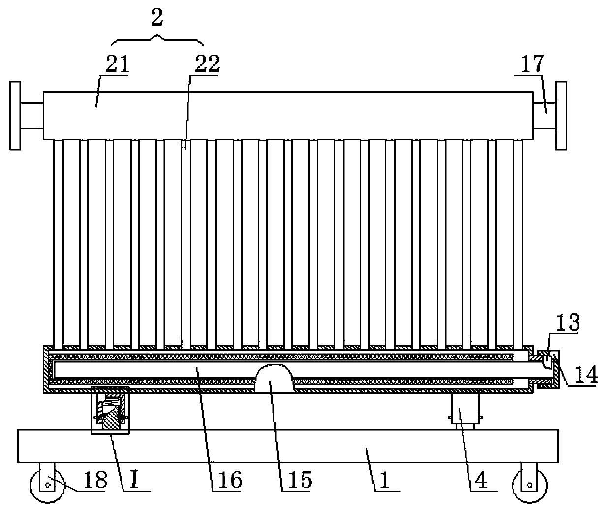
[0015] A skid-mounted heat exchanger circulation device, as shown in the figure, includes a skid-mounted base 1 and a circulation device body 2. The circulation device body 2 is composed of two horizontal thick water pipes 21 and several vertical thin water pipes 22 , the thin water pipes 22 are connected to the inside of the thick water pipe 21, ...


PUM


Abstract

A skid-mounted type heat exchanger circulating device comprises a skid mounted base and a circulating device body. The two sides of the top face of the base are fixedly provided with vertical square blocks. The two sides of the bottom face of the circulating device body are fixedly provided with square caps with open bottom faces. The square caps are in one-to-one correspondence to the square blocks in position. The square blocks can be inserted into the corresponding square caps. The outer periphery of each square block can be in contact and matched with the inner periphery of the corresponding square cap. The upper ends of the square blocks are both fixedly provided with first springs. The upper ends of the first springs are both fixedly provided with square plates. The top faces of thesquare plates can be in contact and matched with the top face inner walls of the corresponding square caps. The skid-mounted type heat exchanger circulating device is easy and rapid to mount and demount, work personnel do not need to sequentially install or detach bolts, the construction time of the work personnel is greatly saved, and therefore the mounting and demounting efficiency of the skid-mounted type heat exchanger circulating device can be greatly improved; and the skid-mounted type heat exchanger circulating device is more convenient to use and suitable for application and popularization.

Description

technical field [0001] The invention belongs to the field of heat exchange equipment, in particular to a skid-mounted heat exchanger circulation device. Background technique [0002] The skid-mounted type refers to an integration method that integrates functional components on a whole base, which can be installed and moved as a whole; among them, the skid-mounted heat exchanger can further simplify the installation process, and further improve the movement and installation efficiency of the heat exchanger , the heat exchanger circulation device is prone to impurities during use, and the accumulation of impurities in the pipeline is easy to cause blockage of the pipeline, resulting in low heat exchange efficiency, so it needs to be disassembled regularly for cleaning and maintenance, but the existing heat exchanger circulation device and pry Most of the connections between the installation bases are bolted connections. Since multiple sets of bolts are required to connect and ...

Claims


Application Information

Patent Timeline
Patent Type & Authority Applications(China)
IPC IPC(8): F16M3/00F16B1/02F16F15/04F28F9/26
CPCF16B1/02F16F15/04F16M3/00F28F9/262
Inventor 刘树亮刘子勇赵红燕宋昊
Owner 中国石化集团胜利石油管理局有限公司新能源开发中心
Why Eureka
Try Eureka