Optical power meter having wide spectral range and great measuring range

An optical power meter, a large range technology, applied in the direction of using an electrical radiation detector for photometry, can solve the problems of low optical power resolution, narrow measurement spectral range, etc., to achieve the effect of broadening the scope of use

Active Publication Date: 2019-07-26
TIANJIN UNIV
View PDF6 Cites 9 Cited by
  • Summary
  • Abstract
  • Description
  • Claims
  • Application Information

AI Technical Summary

Problems solved by technology

[0004] The measurement power range and measurement spectrum range of the optical power meter in the prior art are limited to a certain extent. The photodiode type optical power meter with high optical power resolution has a narrow measurement spectrum range, and the thermoelectric type optical power meter with a wide measurement spectrum range is limited. for lower optical power resolving power

Method used


Image

  • Optical power meter having wide spectral range and great measuring range
  • Optical power meter having wide spectral range and great measuring range
  • Optical power meter having wide spectral range and great measuring range

Examples


Embodiment approach 1

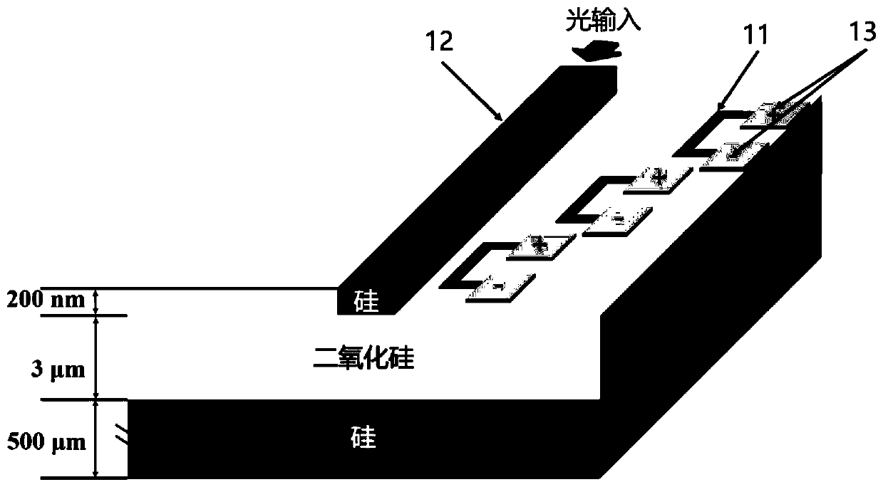
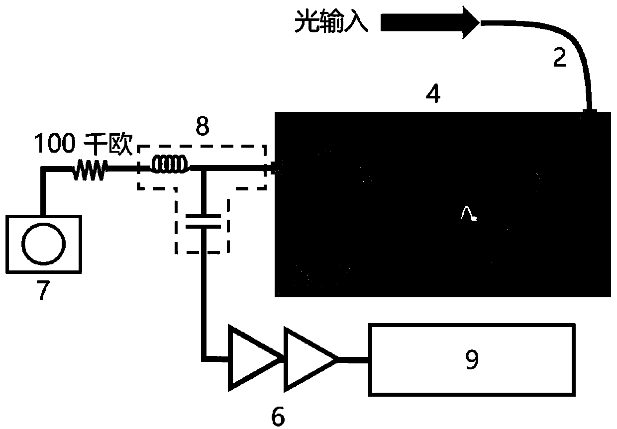
[0053] The light to be measured enters the closed-cycle refrigerator 4 through the single-mode optical fiber 2 and is coupled into the optical waveguide 12 through the optical fiber focuser 3 . A small part of the evanescent wave outside the optical waveguide 12 is absorbed by the superconducting nanowire 11 to form a detection event.

specific Embodiment approach

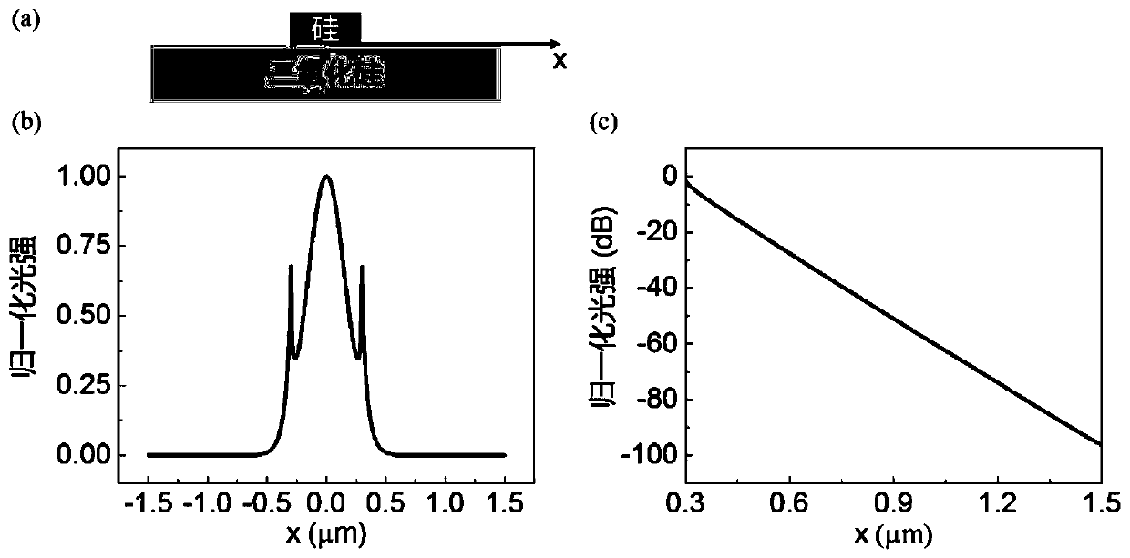
[0055] Working mode one, SNSPD mode. The working temperature is 2.7K. Both ends of the SNSPD are respectively connected with gold electrodes 13 as positive and negative electrodes, and the gold electrodes 13 are connected with the coaxial cable 5 through gold wires. The SNSPD is powered by a low-noise DC voltage source 7 connected in series with a 100 kΩ resistor to form a low-noise constant-current DC source. SNSPD also has a certain count when no detection light is passed through, which is called dark count. The voltage pulse generated by the SNSPD detecting photons is amplified by the low noise amplifier 6 and then connected to the pulse counter 9 . The counting rate obtained by the pulse counter 9 minus the dark count under the light to be measured is multiplied by the energy of the incident single photon, and the evanescent wave light intensity at the position of the SNSPD can be measured, and then determined by the optical waveguide 12 The normalized light intensity c...

Embodiment approach 2

[0059] Calibration of the optical power meter

[0060] The parameters that need to be calibrated in working mode 1 are as follows: the coupling efficiency between the fiber focuser 3 and the optical waveguide 12 at different wavelengths, the normalized curve of the internal and external light intensity of the optical waveguide 12, and the efficiency corresponding to different wavelengths of the SNSPD under the determined bias current.

[0061] The parameters that need to be calibrated in working mode 2 are as follows: the coupling efficiency between the optical fiber focuser 3 and the optical waveguide 12 at different wavelengths, the normalized curve of light intensity inside and outside the optical waveguide 12, and the critical current of the superconducting nanowire 11 versus optical power.

[0062] That is, through the calibration of the above parameters, the measurement accuracy of the optical power meter is improved.


PUM


Abstract

The invention discloses an optical power meter having a wide spectral range and a great measuring range. The optical power meter comprises a photonic superconducting integrated loop detector composedof a superconducting nanowire array and an optical waveguide, wherein the superconducting nanowire array is located on one side of the optical waveguide, each nanowire in the superconducting nanowirearray is spaced apart from the optical waveguide by different distances, and the spacing distance between each nanowire and the optical waveguide is gradually reduced along the propagation direction of the light in the optical waveguide. The optical power meter provided by the invention applies the detector to fundamentally broaden the measurable wavelength range and the measurable power range ofthe optical power meter, and can be widely applied to various optical measurement fields.

Description

technical field [0001] The invention relates to the field of optoelectronic devices, in particular to an optical power meter with a wide spectral range and a large range. Background technique [0002] Optical power meters are commonly used in the fields of optical industrial detection and scientific research. At present, there are two main types of optical power meters commonly used in the market: photodiode type and thermoelectric type. For the photodiode optical power meter, its optical power resolution is nanowatts, but the measurable spectrum is narrow, it can only cover the wavelength range from ultraviolet to near infrared, and the spectrum of a single optical power meter is narrower; for thermoelectric Optical power meter, which can measure the wavelength range from ultraviolet to mid-infrared, but the optical power resolution is low, and the minimum measurement power is several microwatts. [0003] Compared with traditional detectors, photonic superconducting integ...

Claims


Application Information

Patent Timeline
IPC IPC(8): G01J1/42
CPCG01J1/42
Inventor 胡小龙邹锴孟赟冯芃轶胡南许亮兰潇健
Owner TIANJIN UNIV
Why Eureka
Try Eureka