Electronic component temperature detection device

A technology for temperature detection devices and electronic components, which is applied in the direction of measuring devices, measuring device casings, and components of electrical measuring instruments, etc., can solve the problems of slow dynamic test temperature changes, failure to meet test requirements, and large impact, etc., to achieve The effect of controllable conduction direction of temperature field

Inactive Publication Date: 2019-07-26
黄先日
View PDF6 Cites 5 Cited by
  • Summary
  • Abstract
  • Description
  • Claims
  • Application Information

AI Technical Summary

Problems solved by technology

At present, when conducting dynamic tests on electronic equipment, the temperature change test box is generally used. The temperature change test box is equipped with a fan to make the temperature change inside the test box uniform, and there is no fixture for the device under test in the test box; the temperature change test box The temperature of the dynamic test changes slowly and the device or component under test is placed directly in the test chamber, so that it can only heat or cool the test product in a single direction. The temperature change test chamber is mainly suitable for components or devices with large volume and mass
[0003] But in reality, during the normal working process of electronic equipment or electronic components, the heating state is that the heat radiation of the bottom or surrounding heating devices makes the internal temperature of the electronic device rise, especially some electronic components or electronic components with small weight and volume, which are subject to test The impact of temperature changes is greater, and the temperature requirements are higher. When the operating temperature of electronic products changes rapidly and dynamically, the existing dynamic test equipment cannot realize radiation or heat transfer in multiple directions, which cannot meet the test requirements, and is not suitable for simulating electronic products. Use environment requirements

Method used


Image

  • Electronic component temperature detection device

Examples


Embodiment Construction

[0018] In order to enable those skilled in the art to better understand the solution of the present application, the technical solution in the embodiment of the present invention will be clearly described below in conjunction with the drawings in the embodiment of the present invention. Obviously, the described embodiment is the embodiment of the present invention One embodiment, but not all embodiments. Based on the embodiments of the present invention, all other embodiments obtained by persons of ordinary skill in the art without making creative efforts shall fall within the protection scope of the present invention.

[0019] The terms "comprising" and any variations thereof in the description and claims of the present invention and the above drawings are intended to cover non-exclusive inclusion. For example, a process, method or system, product or device comprising a series of steps or units is not limited to the listed steps or units, but optionally also includes steps or...


PUM


Abstract

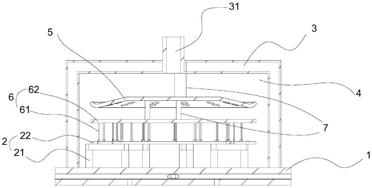
The invention relates to an electronic component temperature detection device. The electronic component temperature detection device comprises a base, a supporting assembly, a compressing assembly, agas flow-guiding plate and an upper cover plate; the base and the upper cover plate form a sealed testing cavity, an air inlet is formed in the upper cover plate, the supporting assembly is located inthe testing cavity and comprises a supporting bracket and a mounting plate in rigid connection with the supporting bracket, and the supporting bracket is mounted on the base; and the compressing assembly is arranged on the upper part of the mounting plate and comprises a compressing suction cup and a compressing suction cup fixing plate, the compressing suction cup fixing plate is fixedly connected with the gas flow-guiding plate, and the gas flow-guiding plate is mounted on the upper cover plate. According to the electronic component temperature detection device, the temperature field conduction direction can be changed according to the requirements of different electronic products, the problem that an original temperature testing box can only heat/cool a testing product unidirectionallyis solved, the temperature field conduction direction can be controlled in the testing process, and the electronic component temperature detection device is especially suitable for dynamic testing ofrapid temperature change of electronic components or electronic products with the small weight and volume.

Description

technical field [0001] The invention belongs to the field of electrical detection devices, in particular to a temperature detection device for electronic components. Background technique [0002] Existing temperature detection devices for electronic products and electronic components are mainly based on static testing, while the temperature field in the working process of electronic products is a dynamic process, and dynamic testing of electronic products is required. At present, when conducting dynamic tests on electronic equipment, the temperature change test box is generally used. The temperature change test box is equipped with a fan to make the temperature change inside the test box uniform, and there is no fixture for the device under test in the test box; the temperature change test box The temperature of the dynamic test changes slowly and the device or component under test is placed directly in the test chamber, so that it can only heat or cool the test product in a...

Claims


Application Information

Patent Timeline
Patent Type & Authority Applications(China)
IPC IPC(8): G01R31/00G01R1/04
CPCG01R1/04G01R1/0425G01R31/001G01R31/003
Inventor 黄先日
Owner 黄先日
Why Eureka
Try Eureka