
Underwater positioning method based on distributed optical fiber sensor

A distributed optical fiber, underwater positioning technology, applied in positioning, instruments, measurement devices, etc., can solve the problems of reducing the accuracy of output time difference, affecting measurement accuracy, and difficult to accurately calculate the time delay of two coherent signals. Boosting, wide-spectrum effects

Active Publication Date: 2019-07-26
HANGZHOU DIANZI UNIV
View PDF13 Cites 0 Cited by
  • Summary
  • Abstract
  • Description
  • Claims
  • Application Information

AI Technical Summary

Problems solved by technology

At present, distributed optical fibers can only be used to locate specific underwater intrusion events, and in signal processing, the time delay of two coherent signals is directly searched in the time domain. Since the disturbance signal in reality is a broadband signal, it is not a certain Single frequency signal, so it is difficult to accurately calculate the time delay of two coherent signals, and its positioning accuracy is also difficult to guarantee
In addition, there are stray noises at each point on the sensing fiber in reality. Due to the influence of these stray noises, the accuracy of measuring the output time difference of the two interference signals is reduced, which seriously affects the measurement accuracy.

Method used


Image

  • Underwater positioning method based on distributed optical fiber sensor
  • Underwater positioning method based on distributed optical fiber sensor
  • Underwater positioning method based on distributed optical fiber sensor

Examples


Embodiment Construction

[0034] The specific implementation method of the underwater positioning system based on distributed optical fibers will be described below in combination with the drawings in the description.

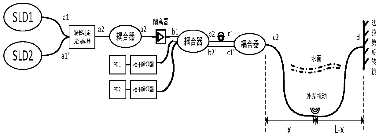
[0035] Such as figure 1 As shown, a kind of underwater positioning method based on distributed optical fiber sensor, the device based on the method includes a first superluminescent light-emitting diode, a second superluminescent light-emitting diode, a wavelength locker and an optical depolarizer, a first coupler, The second coupler, the third coupler, the first isolator, the Faraday rotating mirror, the first coherent demodulator, the second coherent demodulator, the first optical fiber detector PD1, and the second optical fiber detector PD2;

[0036] The first superluminescent light-emitting diode and the second superluminescent light-emitting diode are wavelength-locked by the wavelength locking unit, and then depolarized by the optical depolarizer and passed into the incident end o...


PUM


Abstract

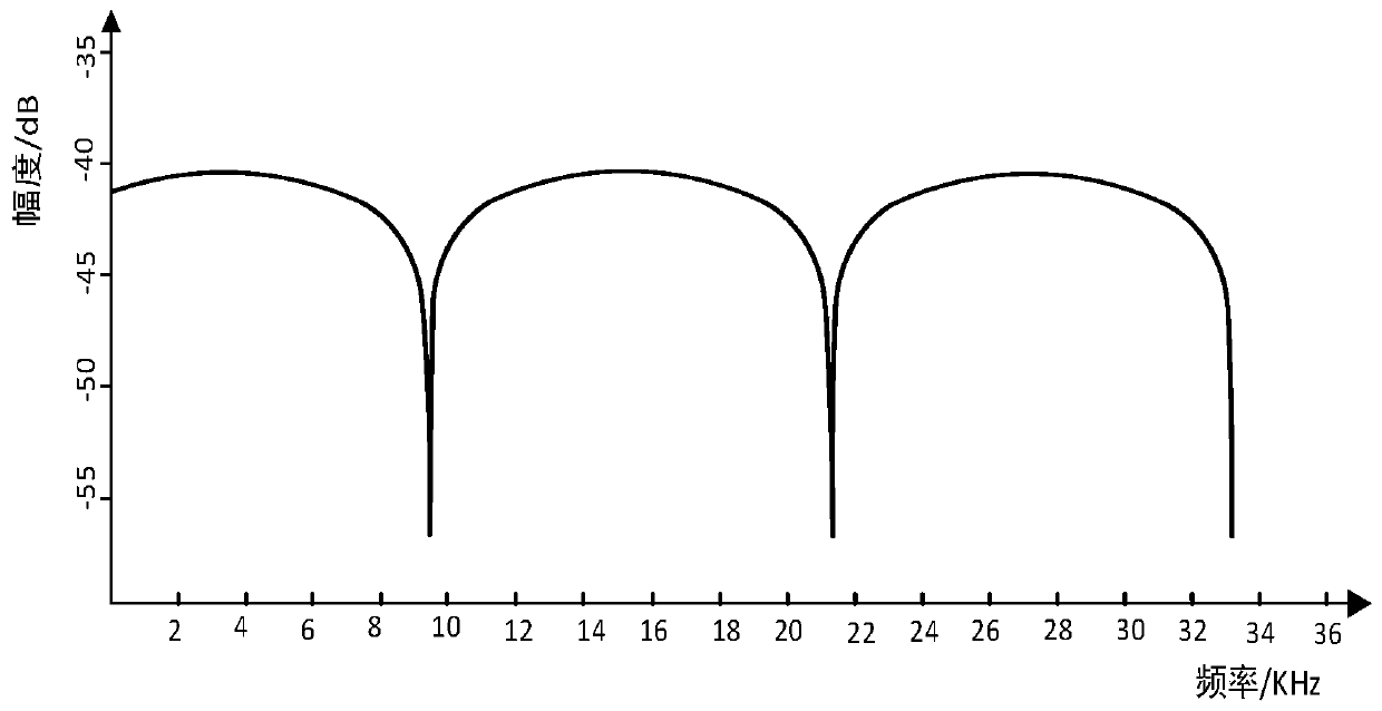
The invention discloses an underwater positioning method based on distributed optical fiber sensor. The invention adopts two superradiance light-emitting diodes with different wavelengths as light source signals. When a disturbance source exists, light source signals can be transmitted with different light paths in the optical fiber path, and due to the fact that a delay coil is added during the design of the underwater positioning system of the distributed optical fiber sensor, two light signals of different light paths reach the coupler 2 with a time difference delta t, and the time difference is related to the position of the disturbance source. Therefore, the coherent signals detected by the photoelectric detection PD 1 and PD 2 contain the position information of the disturbance source, and the position information of the disturbance source is obtained from the spectrogram of the coherent signals through a spectral analysis method. The method of the invention is developed in a frequency domain in the aspect of signal processing, so that the system can detect disturbance signals with a wider frequency spectrum range, and the sensitivity to a disturbance source is improved compared with other data processing methods.

Description

technical field [0001] The invention relates to a long-distance, high-precision real-time positioning technology for an underwater disturbance source by using a distributed optical fiber sensor combined with a spectrum analysis method, in particular to an underwater positioning method based on a distributed optical fiber sensor. Background technique [0002] With the development of economy and society, the number of underwater engineering facilities is increasing year by year, and the economic value is also getting higher and higher. How to take measures to implement protection and obtain perception before destructive behavior is a new technology that is urgently to be invented. At present, distributed optical fibers can only be used to locate specific underwater intrusion events, and in signal processing, the time delay of two coherent signals is directly searched in the time domain. Since the disturbance signal in reality is a broadband signal, it is not a certain Single ...

Claims


Application Information

Patent Timeline
Patent Type & Authority Applications(China)
IPC IPC(8): G01S5/16
CPCG01S5/16
Inventor 杨小岗孔亚广陈张平李闯侯志鹏胡天圣华
Owner HANGZHOU DIANZI UNIV
Learn More