Casting part isolation cooling device

A technology for cooling devices and castings, which is applied in the field of cooling equipment to achieve the effects of reducing workload, easy repair and maintenance, and high efficiency

Inactive Publication Date: 2019-07-30
夏成雷
View PDF8 Cites 3 Cited by
  • Summary
  • Abstract
  • Description
  • Claims
  • Application Information

AI Technical Summary

Problems solved by technology

[0006] The purpose of the present invention is to provide a casting isolation cooling device in order to solve the above problems, which solves the current existing problems

Method used


Image

  • Casting part isolation cooling device
  • Casting part isolation cooling device
  • Casting part isolation cooling device

Examples


Embodiment Construction

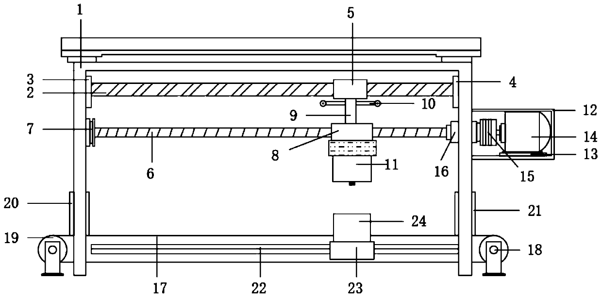
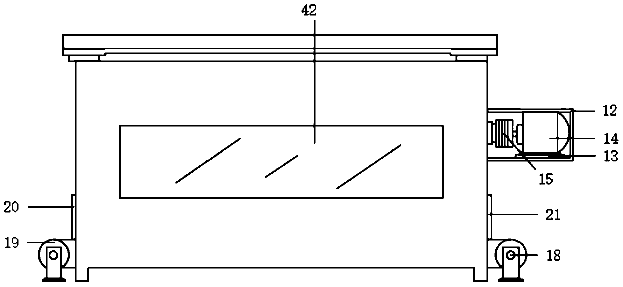
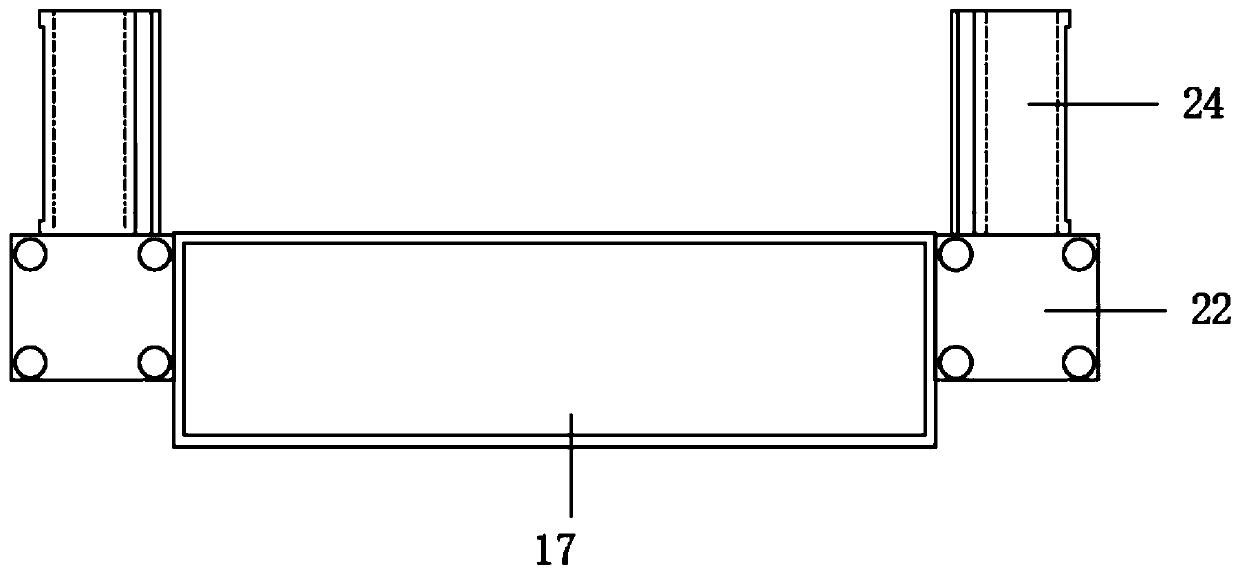
[0026] Such as Figure 1-5 As shown, this specific embodiment adopts the following technical solutions: an isolation cooling device for castings, including a cooling box 1, a transparent observation window 42 is provided on the outer side of the cooling box 1, and a bottom side of the cooling box 1 is provided. There is a No. 2 box door 20, a No. 2 box door 21 is provided on the other side of the cooling box 1 away from the No. 1 box door 20, and a horizontal conveyor belt is provided under the No. 1 box door 20 and the No. 2 box door 21. 17. The end of the horizontal conveyor belt 17 close to the No. 1 box door 20 is connected with a driven wheel 19, and the end of the horizontal conveyor belt 17 close to the No. 2 box door 21 is connected with a driving wheel 18. Both the driving wheel 18 and the driven wheel 19 are Located outside the cooling box 1, the driving wheel 18 is connected to the driven wheel 19 through a horizontal conveyor belt 17, and both sides of the horizont...


PUM


Abstract

The invention discloses a casting part isolation cooling device. The casting part isolation cooling device comprises a cooling box, wherein the outer side surface of the cooling box is provided with atransparent observation window, a first box door is arranged below one side of the cooling box, a second box door is arranged on the other side, away from the first box door, of the lower part of thecooling box, and a horizontal conveying belt is arranged below the first box door and the second box door. By arranging a water spraying and cooling mechanism capable of horizontally moving, sprayingand cooling can be conducted on the casting part which moves on the horizontal conveying belt, and rapid refrigeration can be achieved when the spraying and cooling are undergoing according to the principle that a refrigerant vaporizes and absorbs heat. A evaporation pipe is vertically arranged on one side of a fan, and cold air is blown to the horizontal conveying belt by a fan blade while the refrigerating is undergoing uniformly, therefore the casting part can be rapidly blown and cooled. The casting part isolation cooling device has the advantages of simple structure, high efficiency, easy repairing and maintaining and less workload for constructors, thus greatly improving the operation efficiency.

Description

[0001] Technical field: [0002] The invention belongs to the field of cooling equipment, in particular to an isolated cooling device for castings. [0003] Background technique: [0004] Casting is the method of casting liquid metal into a casting cavity that is suitable for the shape of the part, and after it is cooled and solidified, the method of obtaining the part or blank is called casting. Castings obtained by casting methods are called castings. When designing the casting structure, it is necessary to ensure its working performance and mechanical performance requirements, consider the requirements of the casting process and alloy casting performance on the casting structure, and whether the casting structure design is reasonable or not, the quality of the casting, Productivity and its cost have a great impact. Castings need to be placed indoors to cool them during the production process. After cooling to room temperature, the next step or storage can be carried out. The...

Claims


Application Information

Patent Timeline
Patent Type & Authority Applications(China)
IPC IPC(8): B22D30/00
CPCB22D30/00
Inventor 夏成雷
Owner 夏成雷
Why Eureka
Try Eureka