Chuck expansion type metal hard tube rotary cutting machine

A cutting machine and metal technology, applied in the direction of metal processing equipment, pipe shearing device, shearing device, etc., can solve the problems of radial deformation of steel pipe, unqualified steel pipe, flattening of steel pipe end, etc., and achieve convenient replacement and high cylindricity , Guarantee the effect of versatility

Inactive Publication Date: 2019-07-30
HEBEI UNIV OF TECH
View PDF7 Cites 6 Cited by
  • Summary
  • Abstract
  • Description
  • Claims
  • Application Information

AI Technical Summary

Problems solved by technology

In recent years, drinking water pipes have been laid on a large scale in many areas, and the demand for cutting water pipes has increased sharply. The traditional cutting method of metal hard pipes is to use a grinding wheel cutting machine to cut. For example, the patent application number 201711457096.4 provides a steel pipe cutting device. , can realize fast clamping and cutting of the steel pipe, but because this device needs to completely penetrate the grinding wheel to realize the cutting process of the steel pipe, the grinding wheel will exert a large extrusion force on the steel pipe, and the phenomenon that the end of the steel pipe is often flattened at the cutting place, Cause the steel pipe to be unqualified
The patent application number is 201810255622.7 designed a multi-pipe cutting device, which can realize the simultaneous cutting of three steel pipes and improve the cutting efficiency, but this device will clamp three steel pipes in the same radial direction at the same time, and the excessive extrusion force between the steel pipes will cause Cause radial deformation of the steel pipe

Method used


Image

  • Chuck expansion type metal hard tube rotary cutting machine
  • Chuck expansion type metal hard tube rotary cutting machine
  • Chuck expansion type metal hard tube rotary cutting machine

Examples


Embodiment Construction

[0040] Further explain the present invention below in conjunction with embodiment and accompanying drawing.

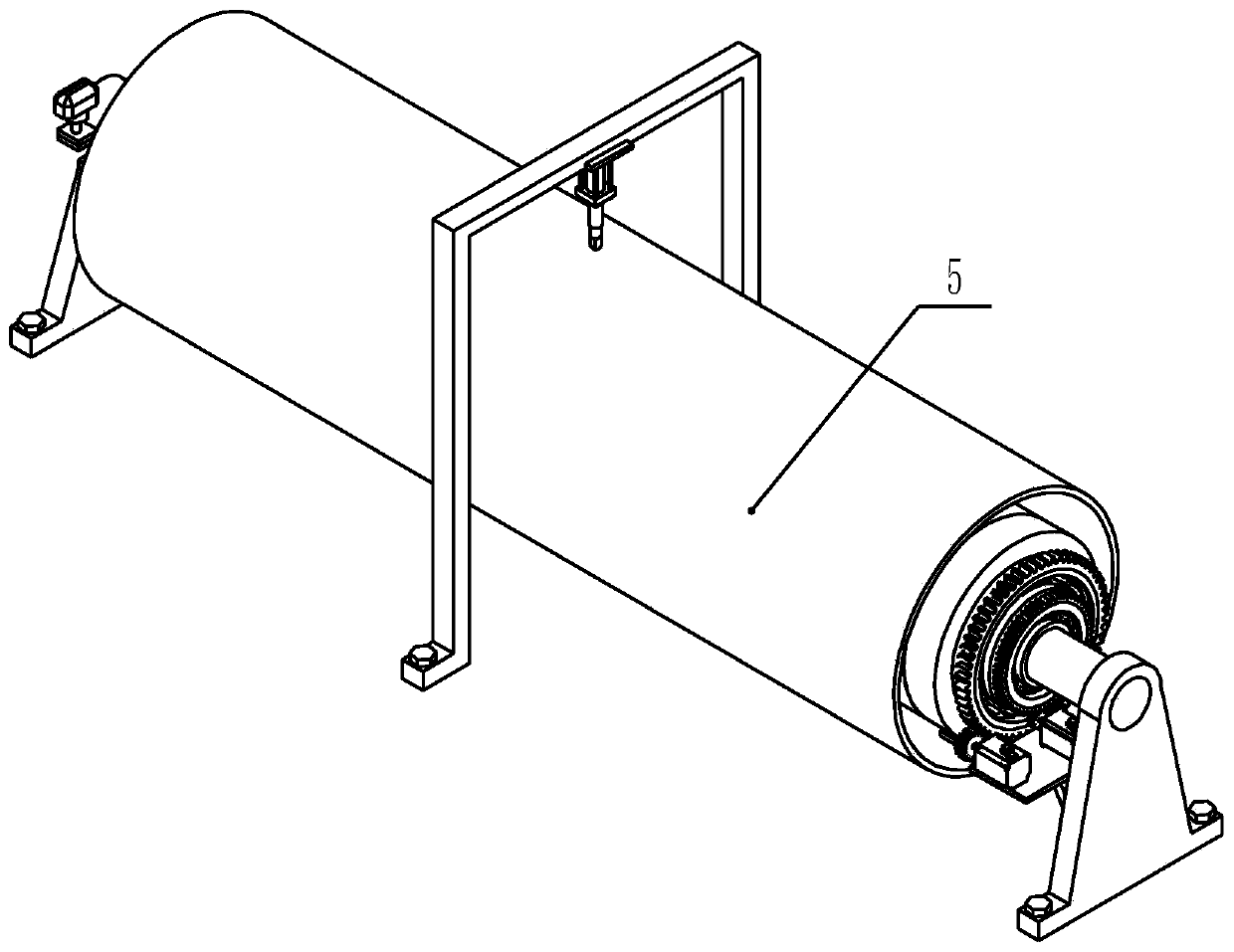
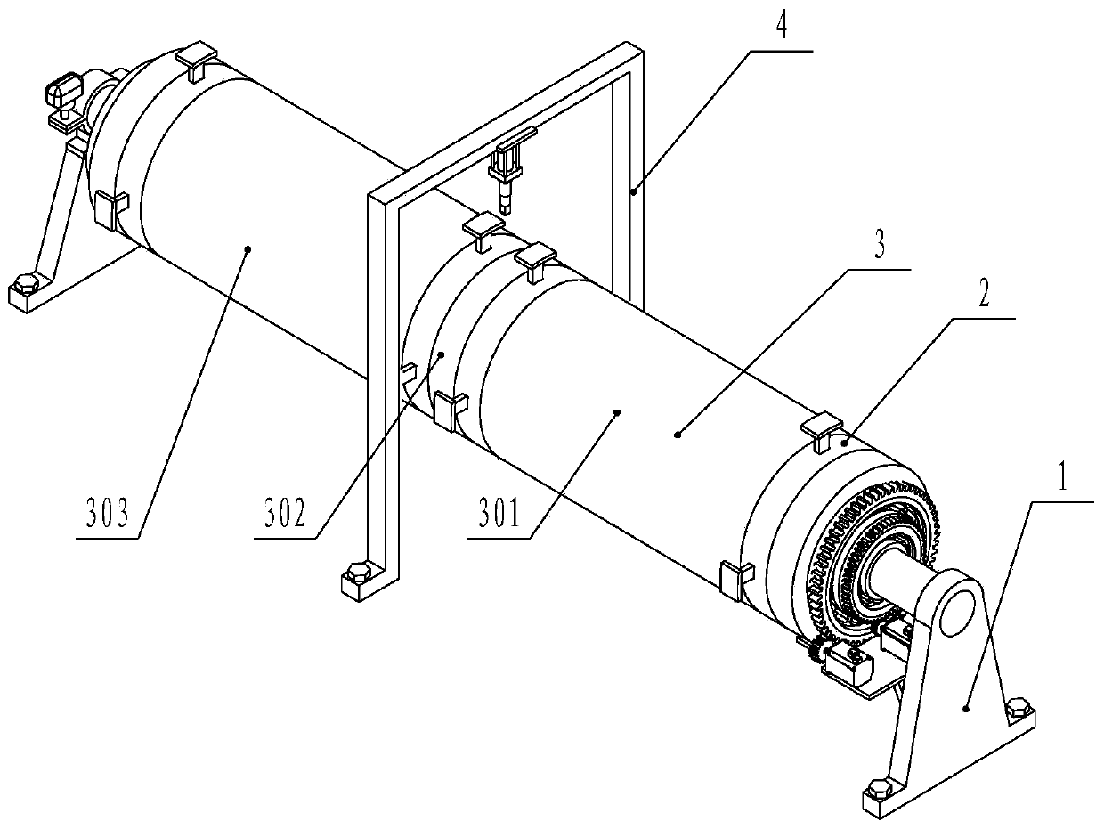
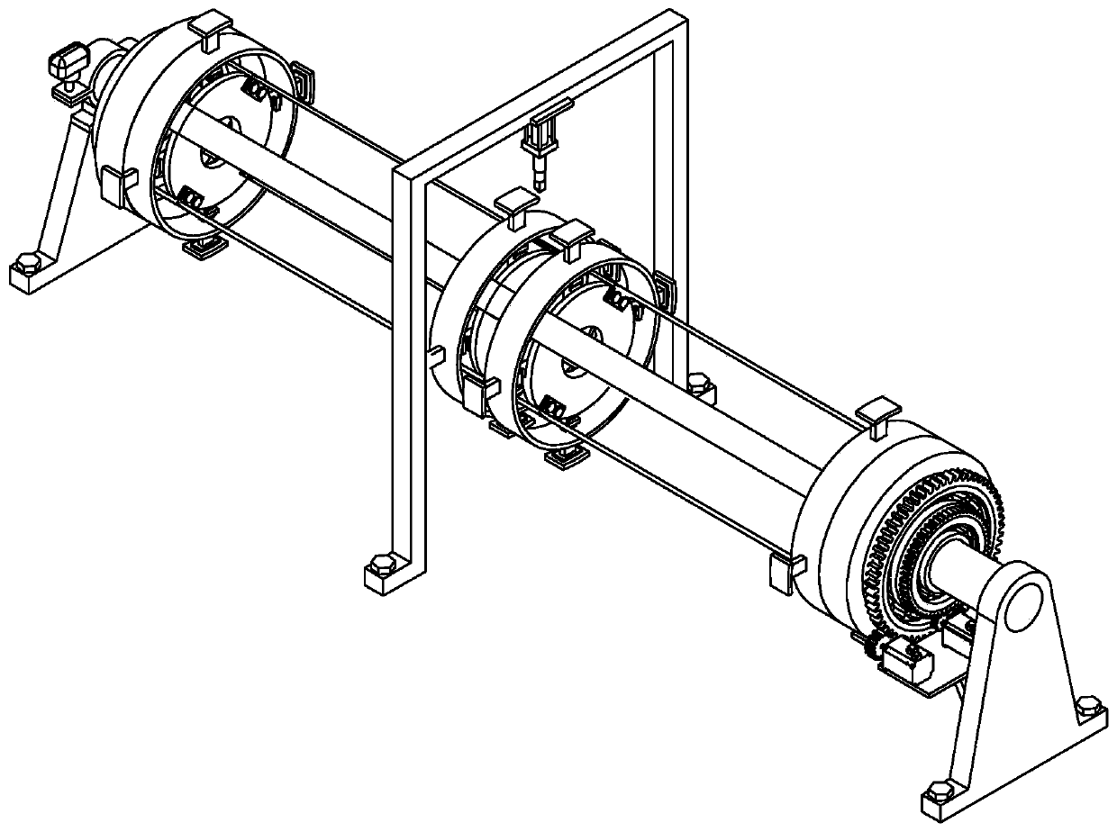
[0041] The present invention is a chuck expansion type metal hard tube rotary cutting machine (referred to as cutting machine, see Figure 1-10 ) includes a support device 1 , an expansion device 2 , a cannula device 3 and a cutting device 4 .

[0042] Described support device 1 comprises front support frame 101, front support shaft 102, inner connection ring 104, outer connection ring 111, advance motor 107, rear travel motor 109, rear support frame 112, large connection ring 115, large bearing 121, small Connecting ring 114, small bearing 113, rear support shaft 117.

[0043] For convenience of description, it is stipulated that the position of the front support frame 101 relative to the rear support frame 112 is front.

[0044] Front support frame 101 is fixed on the ground by anchor bolts, and a circular through hole is arranged on the top of front support frame ...


PUM


Abstract

The invention provides a chuck expansion type metal hard tube rotary cutting machine. The rotary cutting machine comprises a supporting device, a sleeve device, a cutting device and at least four expansion devices, wherein a plurality of expansion devices are sequentially connected and arranged on the same axis through connecting frames, two expansion devices located at two ends are connected withthe supporting device, every two adjacent expansion devices are connected by sleeve pipes of the sleeve device in a sleeving mode, and the cutting device is arranged between two adjacent expansion devices. The expansion devices can expand from the inside of the metal hard tube to achieve the purpose of fixing the metal hard tube, and all lengths of the metal hard tube can be fixed, so that an existing equipment which can only clamp and fix the cut part is replaced, the clamping force is more uniform, and the clamping deformation is prevented; the expansion devices can drive the metal hard tube to rotate together, and then the cutting wall thickness distance can be achieved through feeding movement of a cutting knife, so that the cutting task can be completed, a cutting mode that an existing cutting grinding wheel pieces enter the inner part of the metal hard tube is replaced, and the situation that a cut surface is burned and worn is avoided.

Description

technical field [0001] The invention relates to the technical field of metal hard tube cutting machines, in particular to a chuck expansion type metal hard tube rotary cutting machine. Background technique [0002] With the continuous acceleration of the urbanization process, the people's desire for the construction of rural infrastructure is becoming stronger and stronger. In recent years, drinking water pipes have been laid on a large scale in many areas, and the demand for cutting water pipes has increased sharply. The traditional cutting method of metal hard pipes is to use a grinding wheel cutting machine to cut. For example, the patent application number 201711457096.4 provides a steel pipe cutting device. , can realize fast clamping and cutting of the steel pipe, but because this device needs to completely penetrate the grinding wheel to realize the cutting process of the steel pipe, the grinding wheel will exert a large extrusion force on the steel pipe, and the phen...

Claims


Application Information

Patent Timeline
Patent Type & Authority Applications(China)
IPC IPC(8): B23D21/00B23D33/02
CPCB23D21/00B23D33/02
Inventor 檀润华何川李佳豪杨雯丹董效辰
Owner HEBEI UNIV OF TECH
Why Eureka
Try Eureka