Injection-molding mold lateral parting forced demoulding mechanism scheme

A technology of lateral parting and forced demoulding, which is applied in the field of molding plastic processing, can solve the problems of affecting appearance, inconsistent knocking depth, low efficiency, etc., and achieves the effect of convenient operation and simple structure

Inactive Publication Date: 2019-07-30
嘉兴喜格丽服装有限公司
View PDF5 Cites 3 Cited by
  • Summary
  • Abstract
  • Description
  • Claims
  • Application Information

AI Technical Summary

Problems solved by technology

Specifically, it refers to the high-pressure injection of heated and melted plastic into the mold cavity by the injection molding machine, and after cooling and solidification, a molded product is obtained. During the injection molding process, the molded plastic is often difficult to demould. Therefore, it is necessary to perform forced demoulding. After the plastic is demolded, it needs to be stamped. Users generally use manual knocking, which may easily lead to inconsistent depth of knocking, affect the appearance, and have low efficiency. Therefore, a mechanism scheme for lateral parting of injection molds for forced demoulding is designed. really necessary

Method used


Image

  • Injection-molding mold lateral parting forced demoulding mechanism scheme
  • Injection-molding mold lateral parting forced demoulding mechanism scheme
  • Injection-molding mold lateral parting forced demoulding mechanism scheme

Examples


Embodiment Construction

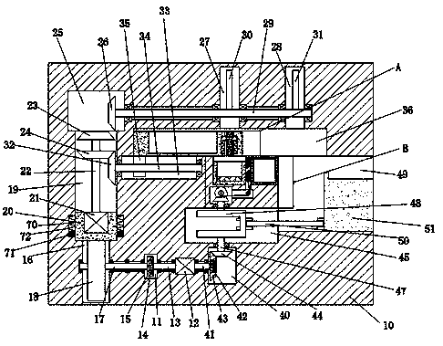
[0013] Combine below Figure 1-3 The present invention is described in detail, and for convenience of description, the orientations mentioned below are now stipulated as follows: figure 1 The up, down, left, right, front and back directions of the projection relationship itself are the same.

[0014] refer to Figure 1-3, according to an embodiment of the present invention, a mechanism scheme for lateral parting and forced demoulding of an injection mold, including a device body 10, a stamp device installed in the device body 10, and a movement device installed in the device body 10 device, the stamp device includes a first rotating chamber 11 arranged in the device main body 10, a first motor 12 is fixedly arranged in the inner wall on the right side of the first rotating chamber 11, and the left end of the first motor 12 is fixedly connected to There is a first rotating shaft 13 extending into the first rotating chamber 11, the first rotating shaft 13 is fixedly connected ...


PUM


Abstract

The invention discloses an injection-molding mold lateral parting forced demoulding mechanism scheme. The injection-molding mold lateral parting forced demoulding mechanism scheme comprises a device main body, a seal stamping device arranged inside the device main body and a moving device arranged inside the device main body, and the seal stamping device comprises a first rotating cavity arrangedinside the device main body. According to the injection-molding mold lateral parting forced demoulding mechanism scheme, at present, indispensable mold stamping and stamping of some mold stamping seals and official seals in the daily office are needed, use staff generally all adopt manual stamping to be prone to causing inconsistent stamping depth, attractiveness is affected, furthermore, the efficiency is low, and the invention aims to design the injection-molding mold lateral parting forced demoulding mechanism scheme that automatic seal stamping performed on molded plastic needing the moldstamping can be finished, and needed stamping ink can be replenished appropriately before the seal stamping every time, sufficient absorption is finished through a sponge foam block, a mold stamping block is guaranteed to be capable of being fully stained with the stamping ink, and meanwhile, coincident mold stamping depth and the clear mold stamping in the mold stamping every time can further beguaranteed.

Description

technical field [0001] The invention relates to the technical field of molding plastic processing, in particular to a mechanism scheme for lateral parting and forced demoulding of an injection mold. Background technique [0002] Injection mold is a tool for producing plastic products; it is also a tool for giving plastic products complete structure and precise dimensions. Injection molding is a processing method used in the mass production of certain complex-shaped parts. Specifically, it refers to injecting the heated and melted plastic into the mold cavity under high pressure from the injection molding machine, and after cooling and solidifying, the molded product is obtained. During the injection molding process, the molded plastic is often difficult to demould. Therefore, it is necessary to perform forced demoulding. After the plastic is removed from the mold, it needs to be stamped. The users generally use manual tapping, which may easily lead to inconsistent depth of ...

Claims


Application Information

Patent Timeline
Patent Type & Authority Applications(China)
IPC IPC(8): B41K3/04B41K3/54
CPCB41K3/04B41K3/54
Inventor 陆利强
Owner 嘉兴喜格丽服装有限公司
Why Eureka
Try Eureka