Ventilating die assembling system with external ring cavity

A ring cavity, outer ring technology, applied in heating/cooling fabrics, textiles and papermaking, fabric surface trimming, etc., can solve the problem of low material utilization rate, and achieve high material utilization rate, improve utilization rate, and reduce waste. Effect

Active Publication Date: 2019-07-30
WUHAN TEXTILE UNIV
View PDF8 Cites 2 Cited by
  • Summary
  • Abstract
  • Description
  • Claims
  • Application Information

AI Technical Summary

Problems solved by technology

[0004] The purpose of the present invention is to overcome the defects and problems existing in the prior art that limit the shape of the molded cotton and the low material u

Method used


Image

  • Ventilating die assembling system with external ring cavity
  • Ventilating die assembling system with external ring cavity
  • Ventilating die assembling system with external ring cavity

Examples


Embodiment 1

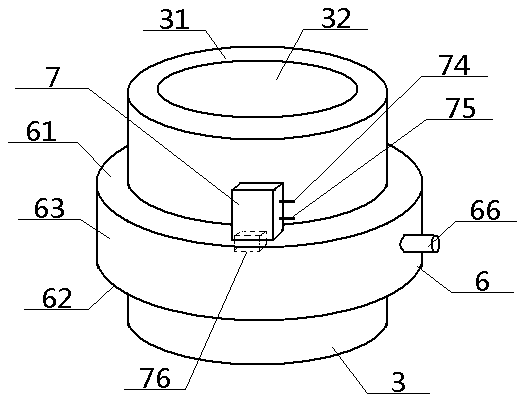
[0058] see Figure 1 to Figure 15 , a peripheral ring-cavity ventilation mold clamping system, including an outer sleeve 4, an upper mold 2 and a lower mold 3, the outer sleeve 4 is a hollow structure, and the upper mold 2 includes an upper mold body 21 and its interior The upper mold cavity 22 opened, the lower mold 3 includes the lower mold body 31 and the lower mold cavity 32 opened inside, the upper mold cavity 22, the lower mold cavity 32 are butted up and down to form a molding cavity 1, and the outer sleeve 4 The width of the inner wall is greater than the width of the upper mold 2 and the lower mold 3; the inside of the upper mold body 21 is provided with a plurality of upper air passages 25 communicating with the upper mold cavity 22, and the outer end of the upper air passage 25 is connected to the upper mold 2. The external environment communicates, and the inside of the lower mold body 31 is provided with a plurality of lower air passages 35 communicating with the ...

Embodiment 2

[0060] Basic content is the same as embodiment 1, the difference is:

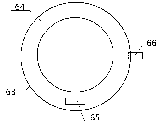
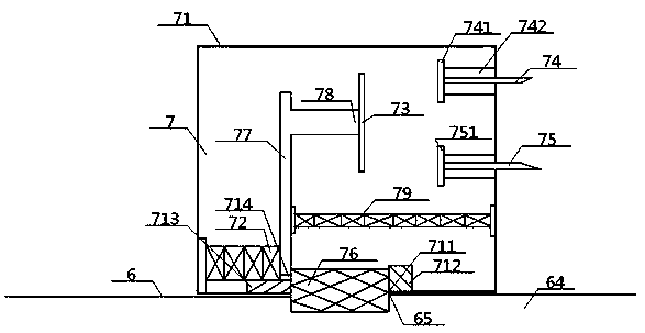
[0061] The temperature monitor 7 includes a monitoring shell 71, a compression spring 72, a movable conductive sheet 73, an upper conductive wire 74, a lower conductive wire 75, and a monitoring wax block 76. A container opening 711 is provided at the bottom of the monitoring shell 71. A monitoring wax block 76 is embedded in the content opening 711. The top surface of the monitoring wax block 76 is located in the monitoring shell 71. The bottom surface of the monitoring wax block 76 passes through the monitoring port 65 and is located inside the outer ring cavity 64. The monitoring wax block The left end of 76 is bonded to one side of the lower part of the insulating vertical bar 77, the other side of the lower part of the insulating vertical bar 77 is fixedly connected to one end of the compression spring 72, and the other end of the compression spring 72 is connected to the left wall of the monitoring hou...

Embodiment 3

[0063] Basic content is the same as embodiment 1, the difference is:

[0064] The top surface of the upper mold body 21 is connected with the lower pressing shaft 20, and the bottom surface of the upper mold body 21 is provided with a concentric upper inner slide rail 23 and an upper outer slide rail 24 around the position of the upper mold cavity 22. The rail 23 and the upper and outer slide rails 24 are all ring structures, and the top surface of the lower mold body 31 is provided with a concentric lower inner chute 33 and a lower outer chute 34 around the lower mold cavity 32. The groove 33 and the lower outer chute 34 are all annular structures, the lower inner chute 33 is slidably matched with the upper inner slide rail 23 inserted into its interior, and the lower outer chute 34 is slidably matched with the upper outer slide rail 24 inserted into its interior . The structures of the upper inner slide rail 23 and the upper outer slide rail 24 are consistent, and both incl...


PUM


Abstract

The invention discloses a ventilating die assembling system with an external ring cavity. The ventilating die assembling system comprises an outer sleeve, an upper die and a lower die, wherein the height of the outer sleeve is greater than that of the upper die; the bottom end of the outer sleeve is located between the top surface of a lower die body and an outer ring body; each of the upper and lower dies comprises an external die body and an internal die cavity; a plurality of upper ventilating passages communicated with the upper die cavity are formed in the upper die body; a plurality of lower ventilating passages communicated with the lower die cavity are formed in the lower die body; the outer ends of the lower ventilating passages pass through an air inlet region arranged on the bottom surface of the lower die and then are communicated with an air outlet of an air jet device; the outer ring body of the hollow structure is arranged on the outer side wall of the lower die; the outer ring body comprises an outer ring top surface, an outer ring bottom surface and an outer ring side wall; the outer ring top surface, the outer ring side wall, the outer ring bottom surface and theouter wall of the lower die body jointly form one outer ring cavity in an encircling manner; a monitoring port connected with a temperature monitor is formed in the top surface of the outer ring. Thedesign does not limit the shape of formed cotton, can increase the material utilization rate and is relatively high in controllability.

Description

technical field [0001] The invention relates to a mold clamping device, which belongs to the field of textile machinery, and in particular to a peripheral ring-cavity ventilation mold clamping system, which is particularly suitable for not limiting the shape of molded cotton and improving the utilization rate of materials. Background technique [0002] At present, shaped cotton made of textile fibers is used in many fields, such as filling, lining support, etc. Textile fibers include natural fibers and chemical fibers. As for how to make textile fibers into shaped cotton with stable structure, most of the existing technologies are to open the textile fibers through raw materials, comb them into a web, and then perform various processing, such as warp and weft weaving, layer-by-layer stacking, and vertical / horizontal web laying. Or their combination, and finally dry and cool to obtain shaped cotton. It can be seen that the existing technology not only has a long processing fl...

Claims


Application Information

Patent Timeline
IPC IPC(8): D04H1/76D04H1/54D06C7/02
CPCD04H1/54D04H1/76D06C7/02
Inventor 张智明王佳伟徐巧姬巧玲梅顺齐肖人彬
Owner WUHAN TEXTILE UNIV
Why Eureka
Try Eureka