
Snow-removinganddeicing vehicle

A technology for de-icing vehicles and frames, which is applied in snow surface cleaning, construction, cleaning methods, etc., and can solve the problems of busy people, low efficiency, hidden dangers to pedestrians and vehicles, etc.

Inactive Publication Date: 2019-07-30
LANZHOU INST OF TECH
View PDF0 Cites 0 Cited by
  • Summary
  • Abstract
  • Description
  • Claims
  • Application Information

AI Technical Summary

Problems solved by technology

[0002] In cold winter, rainy and snowy weather, it is easy to freeze and snow on the road, which brings great safety hazards to pedestrians and vehicles. Pedestrians are easy to fall, vehicles are easy to slip, and the braking distance increases, even Unable to brake, skidding occurs, the direction of the vehicle is out of control, and road traffic accidents are prone to occur, causing personal injuries and other dangerous situations. Once ice and snow accumulate on the expressway, it needs to be closed
As an important channel and mode of land transportation, expressways, once closed, will bring great inconvenience to people's travel and transportation in production and life, and cause losses to the country's fiscal revenue.
Traditional snow removal and deicing usually use artificial distribution of industrial salt. On the one hand, the melting of ice and snow is slow and the efficiency is low. On the other hand, the melted ice and snow still remain on the road surface, accompanied by a large amount of snow water, which is ineffective and poses a hidden danger to driving safety. larger

Method used


Image

  • Snow-removinganddeicing vehicle
  • Snow-removinganddeicing vehicle
  • Snow-removinganddeicing vehicle

Examples


Embodiment Construction

[0013] The technical solution of the present invention will be described in more detail below in conjunction with the accompanying drawings.

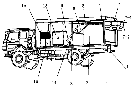
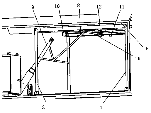
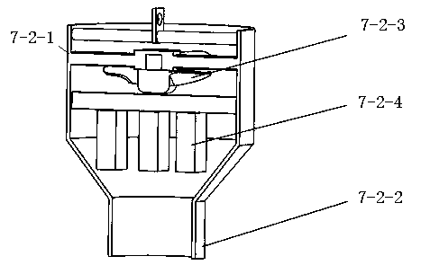
[0014] Such as figure 1 and figure 2 As shown, a snow removal and deicing vehicle provided in this embodiment includes a vehicle frame 1 on which a shelter 2 is fixedly installed, and two first connecting frames are symmetrically arranged in the shelter 2 Rod 3, two second connecting rods 4 and two slide rails 5, one end of the first connecting rod 3 is hinged with the bottom surface of the shelter 2, and the other end is hinged with one end of the slide rail 5, and the slide rail The other end of 5 is hinged with one end of the second connecting rod 4, the other end of the second connecting rod 4 is hinged with the bottom surface of the shelter 2, and the two slide rails 5 are connected by a sliding pair A hanger rod 6 is installed, and the air duct pendant assembly 7 is fixed on the hanger rod 6, and a V-shaped connecting rod 8 is ...


PUM


Abstract

The invention relates to a snow-removingand deicing vehicle, which comprises a vehicle frame of a vehicle, a square cabin is fixedlymounted on the vehicle frame, and first frame connecting rods, second frame connecting rods, and sliding railsare arranged in the square cabin;one ends of the first frame connecting rodsare hinged to the bottom surface of the square cabin, and the other endsare hingedto one ends of the sliding rails; the other ends of the sliding railsare hinged to one ends of the second frame connecting rods, and the other ends of the second frame connecting rodsare hinged to the bottom surface of the square cabin;frame hanging rods are mounted between the sliding railsthrough sliding pairs, airduct hanging assemblies are fixed on the frame hanging rods, a V-shaped frame connecting rod is fixedly connected between two first frame connecting rods, and the V-shaped frame connecting rod, a hydraulic cylinder, and the frame hanging rods are connected; first electromagnets and second electromagnetsare arranged on the top of the square bin, the first electromagnetsare mounted at the end parts of the vertical positions of the first frame connecting rods, the second electromagnets are mounted on the sliding rails, limiting blocksare arranged on the frame hanging rods. According to the snow-removingand deicing vehicle,a whole deicing and snow-removing component can be placed in the square cabin whilehigh-temperature deicing and snow-removing are realized, and the effects of windproof, rainproof, and dampproof are realized.

Description

technical field [0001] The invention relates to a snow and ice removal vehicle, which belongs to the technical field of road surface ice and snow cleaning. Background technique [0002] In cold winter, rainy and snowy weather, it is easy to freeze and snow on the road, which brings great safety hazards to pedestrians and vehicles. Pedestrians are easy to fall, vehicles are easy to slip, and the braking distance increases, even Unable to brake, skidding occurs, the direction of the vehicle is out of control, and road traffic accidents are prone to occur, causing personal injuries and other dangerous situations. Once ice and snow accumulate on the expressway, it needs to be closed. As an important channel and mode of land transportation, highways, once closed, will bring great inconvenience to people's travel and transportation in production and life, and cause losses to the country's fiscal revenue. Traditional snow removal and deicing usually use artificial distribution of ...

Claims


Application Information

Patent Timeline
Patent Type & Authority Applications(China)
IPC IPC(8): E01H5/10
CPCE01H5/106
Inventor 王亮林晓军牛玉艳张亚萍李敏易湘斌沈建成李晓青郭志成
Owner LANZHOU INST OF TECH
Learn More