
Device for testing current of electronic lock

A testing device and electronic lock technology, applied in the field of testing, can solve the problems of increasing the difficulty of testing, malfunctioning of electronic locks, reducing testing accuracy, etc., to achieve the effects of improving testing efficiency, simplifying testing process, and not easy to malfunction

Inactive Publication Date: 2019-07-30
KUNSHAN BRANCH INST OF MICROELECTRONICS OF CHINESE ACADEMY OF SCI
View PDF5 Cites 0 Cited by
  • Summary
  • Abstract
  • Description
  • Claims
  • Application Information

AI Technical Summary

Problems solved by technology

At present, ammeters with ordinary ranges cannot accurately read the current that needs to be displayed when it exceeds two orders of magnitude
In the prior art, microampere ammeters and milliampere ammeters are usually used to jointly test the current of electronic locks. However, the two ammeters can only be manually switched according to the state of the electronic lock, which makes the test process more cumbersome and reduces the test efficiency; During the switching process of the two ammeters, the power supply current of the electronic lock will be discontinuous, which will easily cause the electronic lock to malfunction, increase the difficulty of the test, and reduce the accuracy of the test.

Method used


Image

  • Device for testing current of electronic lock
  • Device for testing current of electronic lock
  • Device for testing current of electronic lock

Examples


Embodiment Construction

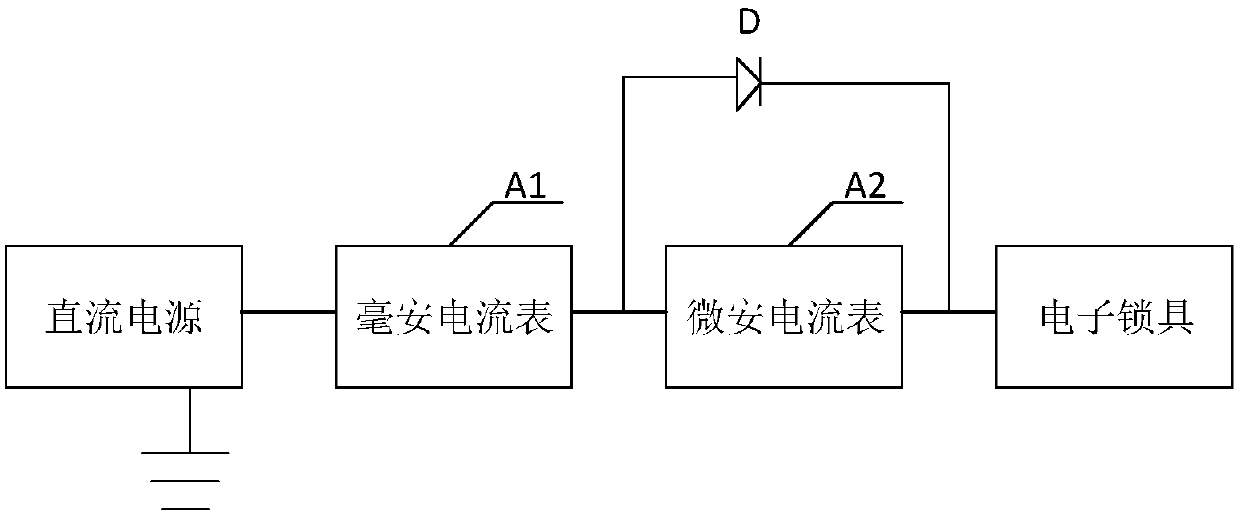
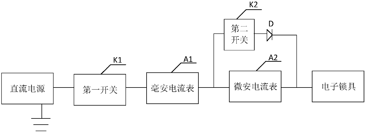
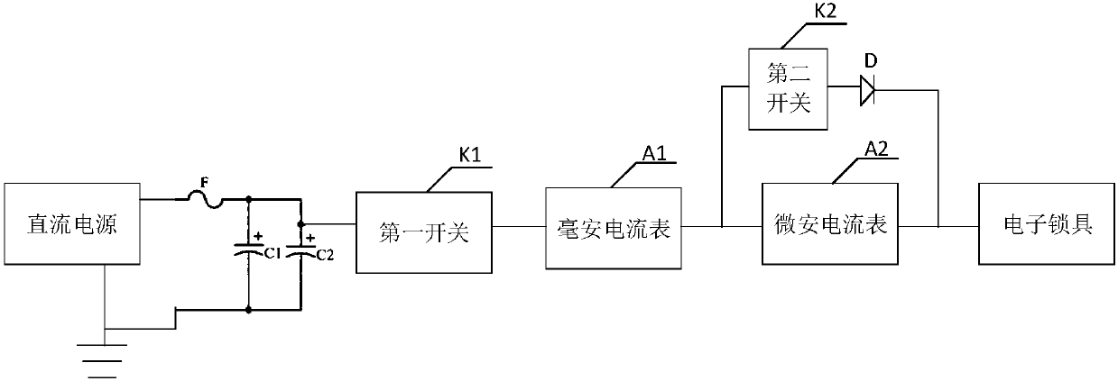
[0021] The core of the present invention is to provide a testing device for electric lock current, which can automatically switch between two ammeters according to the state of the electronic lock, thereby simplifying the testing process and improving test efficiency; and during the switching process of the two ammeters, no As a result, the power supply current of the electronic lock is discontinuous, and it is not easy to cause a malfunction of the electronic lock, which reduces the difficulty of testing and improves the accuracy of testing.

[0022] In order to make the purpose, technical solutions and advantages of the embodiments of the present invention clearer, the technical solutions in the embodiments of the present invention will be clearly and completely described below in conjunction with the drawings in the embodiments of the present invention. Obviously, the described embodiments It is a part of embodiments of the present invention, but not all embodiments. Based ...


PUM


Abstract

The invention discloses a device for testing a current of an electronic lock. The device comprises a milliampere ampere meter, a microampere ampere meter and a diode used for being disconnected duringinflow of a microampere current and being connected during inflow of a milliampere current, wherein the positive output end of a direct-current power source is connected with the input end of the milliampere ampere meter, the negative output end of the direct-current power source is grounded, the output end of the milliampere ampere meter is connected with the input end of the microampere amperemeter and an anode of the diode, and a cathode of the diode is connected with the output end of the microampere ampere meter and the electronic lock. It can be seen that the two ampere meters can be automatically switched according to the state of the electronic lock, thus the testing process is simplified, and the testing efficiency is improved; and in the switching process of the two ampere meters, the incontinuity of the power supply current of the electronic lock is avoided, misoperation of the electronic lock is not liable to be caused, testing difficulty is lowered, and testing accuracyis improved.

Description

technical field [0001] The invention relates to the technical field of testing, in particular to a testing device for electric lock current. Background technique [0002] With the development of intelligent technology, traditional locks have been gradually replaced by electronic locks. Electronic locks are a new type of smart locks used for security, which can open doors through fingerprints, passwords and smart cards. Due to the particularity of its working nature, electronic locks have a relatively large working current span. When the electronic lock is dormant, its minimum operating current can be as small as several μA; and when the user needs to open the door and the electronic lock is awakened, its maximum operating current can reach hundreds of mA or even higher, and the current span can reach 5 orders of magnitude. At present, an ammeter with a common range cannot accurately read the current to be displayed when it exceeds two orders of magnitude. In the prior art...

Claims


Application Information

Patent Timeline
IPC IPC(8): G01R19/00G01R15/09
CPCG01R15/09G01R19/0092
Inventor 张飞飞卢孟周斌
Owner KUNSHAN BRANCH INST OF MICROELECTRONICS OF CHINESE ACADEMY OF SCI
Learn More