
Microphone array method for sound source localization

A technology for microphone array and sound source localization, applied in the field of microphone array for sound source localization, can solve the problems of complex localization algorithm, affecting the real-time performance of localization, high computational complexity, etc., and achieves improved distance localization accuracy, high engineering application value, The effect of improving the ranging performance

Inactive Publication Date: 2019-07-30
TIANJIN UNIV
View PDF5 Cites 7 Cited by
  • Summary
  • Abstract
  • Description
  • Claims
  • Application Information

AI Technical Summary

Problems solved by technology

The three-dimensional five-element array, six-element positive quadrilateral pyramidal array, and seven-element spatial cross array models only have numerical simulations compared with planar quaternary arrays or planar five-element arrays, and it is impossible to comprehensively consider the accuracy and robustness of the positioning performance of several models
Moreover, its positioning accuracy is greatly affected by the environment, and its positioning performance needs to be improved
On the one hand, the larger the number of microphones, the higher the positioning accuracy and the better the system performance. However, if the number of microphones is too large, the volume of the array will be increased to a certain extent, which will increase the difficulty of system implementation and make the positioning algorithm complicated. It leads to high computational complexity and affects the real-time performance of positioning.

Method used


Image

  • Microphone array method for sound source localization
  • Microphone array method for sound source localization
  • Microphone array method for sound source localization

Examples


Embodiment Construction

[0037] A microphone array method for sound source localization according to the present invention will be described in detail below with reference to the embodiments and the accompanying drawings.

[0038] A kind of microphone array method for sound source localization of the present invention comprises the following steps:

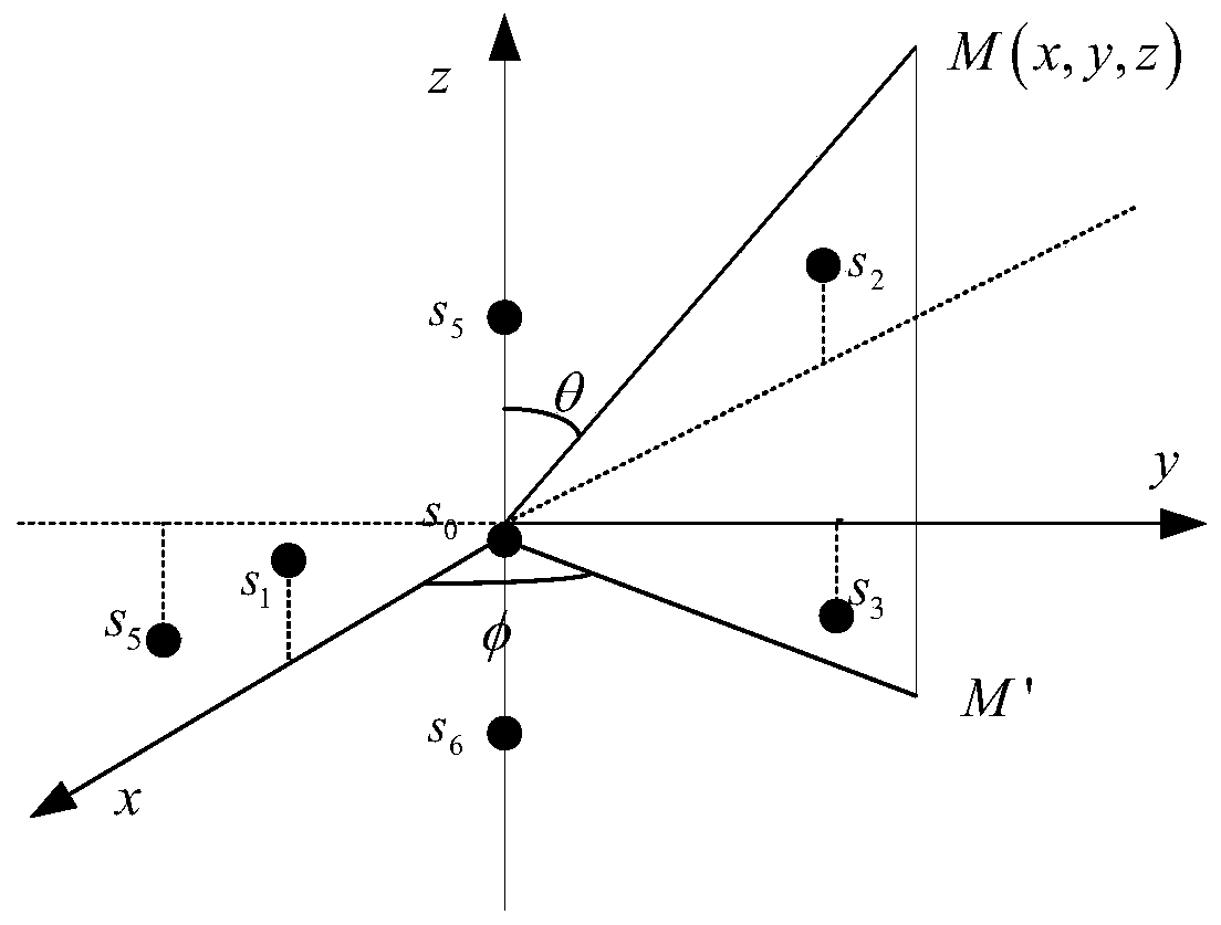
[0039] 1) Set the positions of the spatial distribution of the seven microphones in the seven-element stereo microphone array, such as figure 1 Shown:

[0040] the s 0 (0,0,0),s 1 (d,0,d),s 2 (-d,0,d),s 3 (0,d,-d),s 4 (0,-d,-d), s 5 (0,0,d),s 6 (0,0,-d)

[0041] Among them, s 0 is the microphone at the origin, s 1 ~s 6 are 6 microphones distributed at other positions than the origin, d is s 1 ~s 6 the distance from the coordinate axis;

[0042] 2) establish the mathematical model of microphone array according to the position of seven microphone spatial distributions:

[0043]

[0044] Among them, τ i is the sound source arriving at the ...


PUM


Abstract

A microphone array method for sound source localization comprises steps of setting spatial distribution positions of seven microphones in a seven-element stereoscopic microphone array: s0 (0, 0, 0), s1 (d, 0, d), s2 (-d, 0, d), s3 (0, d, -d),s4 (0, -d, -d), s5 (0, 0, d), s6 (0, 0, -d), wherein, s0 is the microphone at the origin, s1-s6 are 6 microphones distributed at other positions rather than the origin, and d is the distance from s1- s6 to the coordinate axis; establishing a mathematical model for the microphone array according to the spatial distribution positions of the seven microphones; solving the mathematical model and determining the location of the sound source. The microphone array method for sound source localization can effectively improve the ranging performance on the basis of keeping the array size and the number of microphones unchanged and not sacrificing the positioning performances of the pitch angle and the direction angle. The array formation has a better good effect on the positioning of the pitch angle and the direction angle, so as to effectively improve the accuracy of distance positioning while keeping the advantages of high positioning accuracy at thepitch angle and the direction angle in the spatial cross stereoscopic array.

Description

technical field [0001] The invention relates to a microphone array. In particular it relates to a microphone array method for sound source localization. Background technique [0002] In the TDOA-based sound source localization algorithm, the localization accuracy is mainly affected by factors such as the arrangement of the microphone array and the number of microphones. In the past research, the common microphone array method arrays applied to sound source localization mainly include: planar four-element array, planar five-element array in the planar array, and three-dimensional five-element array and six-element regular quadrilateral array in the non-planar array. Cone array, and seven-element space intersection array, etc. The three-dimensional five-element array, six-element positive quadrilateral pyramidal array, and seven-element spatial cross array models only have numerical simulations for comparison with the planar quaternary array or planar five-element array, and...

Claims


Application Information

Patent Timeline
Patent Type & Authority Applications(China)
IPC IPC(8): G01S5/20G06F17/12
CPCG01S5/20G06F17/12
Inventor 张涛焦琛
Owner TIANJIN UNIV
Learn More