Structural light projection device

A technology of structured light projection and light, applied in projection devices, optics, optical components, etc., can solve problems such as thermal deformation, low light quality, and poor collimated beam effect of collimating lenses

Pending Publication Date: 2019-07-30
NINGBO SUNNY OPOTECH CO LTD
View PDF0 Cites 2 Cited by
  • Summary
  • Abstract
  • Description
  • Claims
  • Application Information

AI Technical Summary

Problems solved by technology

Traditional collimator lenses are sensitive to heat, which can easily lead to thermal deformation or thermal expansion, which makes the collimated beam effect of the collimator lens worse, which in turn leads to low quality of structured light formed by the entire structured light projection device, and ultimately affects the entire The imaging effect of the depth camera has adverse effects

Method used


Image

  • Structural light projection device
  • Structural light projection device
  • Structural light projection device

Examples


Embodiment 1

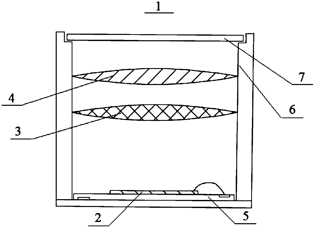
[0080] Refer to the following figure 1 Embodiment 1 of the structured light projection device of the present application will be described.

[0081] Such as figure 1 As shown, Embodiment 1 of the structured light projection device 1 includes a laser emitting part 2 , a first collimating lens 3 and a second collimating lens 4 . The first collimating lens 3 is located on the optical path of the light emitted by the laser emitting part 2 to initially collimate the light emitted by the laser emitting part 2 . The second collimator lens is located on the optical path of the light rays initially collimated by the first collimator lens 3 to re-collimate the light rays initially collimated by the first collimator lens 3 to form parallel light beams. The laser emitting part 2 is located on the plane where the focal point jointly formed by the first collimating lens 3 and the second collimating lens 4 is located.

[0082] In Embodiment 1, the structured light projection device 1 furt...

Embodiment 2

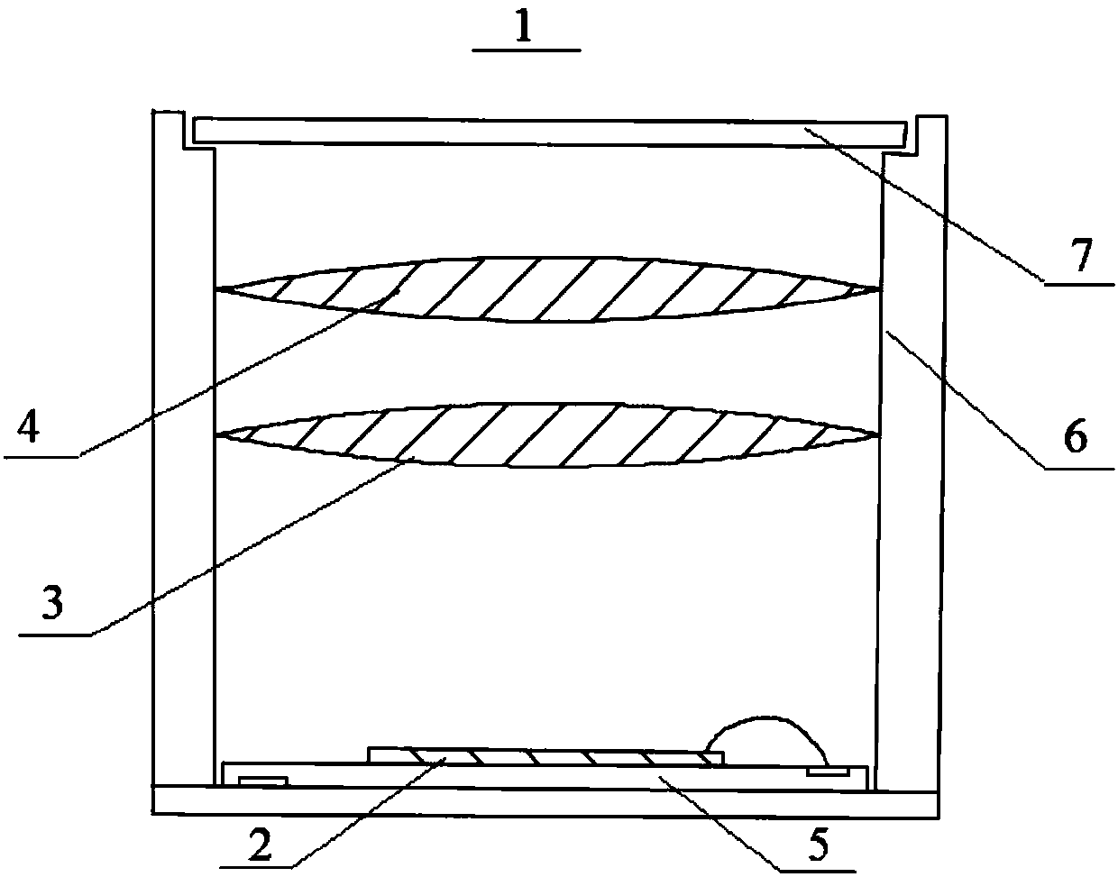
[0088] Refer to the following figure 2 Embodiment 2 of the structured light projection device 1 of the present application is described. Except for the material of the first collimating lens 3 , the arrangement structure of the structured light projection device 1 described in Embodiment 2 and the following Embodiment 3 is the same as that of the structured light projection device described in Embodiment 1. For the sake of brevity, part of the description similar to Embodiment 1 will be omitted.

[0089] figure 2 A schematic structural diagram of the structured light projection device 1 of Embodiment 2 is shown. Such as figure 2 As shown, the first collimating lens 3 and the second collimating lens 4 of the structured light projection device 1 according to Embodiment 2 are both made of a material with high thermal stability, such as glass.

Embodiment 3

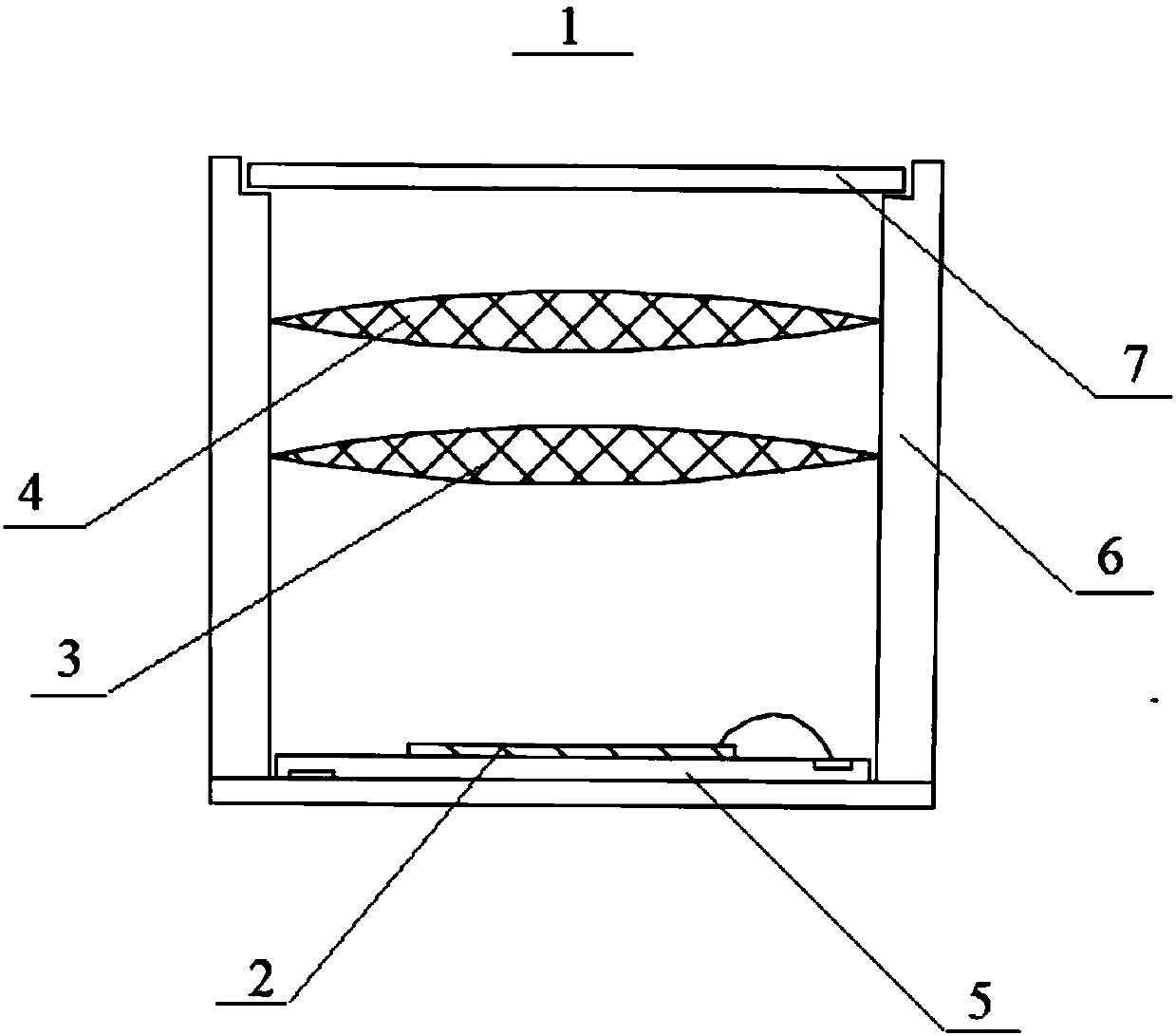
[0091] Refer to the following image 3 Embodiment 3 of the structured light projection device 1 of the present application is described. image 3 A schematic structural diagram of the structured light projection device 1 of Embodiment 3 is shown. Such as image 3 As shown, the first collimating lens 3 and the second collimating lens 4 of the structured light projection device 1 according to Embodiment 3 are both made of conventional collimating lens materials with low thermal stability, such as plastic.


PUM


Abstract

The invention provides a structural light projection device. The structural light projection device comprises a laser emission part, a first collimating lens, a second collimating lens and a diffraction optical part, wherein the first collimating lens is arranged on a light path of a light ray emitted from the laser emission part so as to initially collimate the light ray emitted from the laser emission part, the second collimating lens is arranged on a light path of a light ray initially collimated by the first collimating lens so as to collimate the light ray, initially collimated by the first collimating lens, again and form parallel light beams, the diffraction optical part is arranged at one side, far away from the laser emission part, of the second collimating lens so that a light ray passing through the second collimating lens is projected to a surface of a target space.

Description

technical field [0001] The present application relates to a structured light projection device, in particular to a structured light projection device having at least two collimating lenses, a depth camera configured with the structured light projection device, and an electronic device configured with the depth camera. Background technique [0002] As is well known in the art, a depth camera can acquire depth information of a photographed target, thereby enabling functions such as 3D scanning, imaging, and modeling. The depth camera technology is becoming more and more perfect, and has gradually attracted the attention of various industries. It has begun to appear on a large number of electronic devices, bringing people a better shooting experience. [0003] As an important component of the depth camera, the function of the structured light projection device directly affects the function of the entire depth camera. For example, the poor projection effect of the structured lig...

Claims


Application Information

Patent Timeline
Patent Type & Authority Applications(China)
IPC IPC(8): G03B21/20G03B17/54G02B1/00G02B27/30
CPCG03B21/208G03B17/54G02B1/00G02B27/30
Inventor 姚立锋陈飞帆潘民杰徐毅杰刘筱迪
Owner NINGBO SUNNY OPOTECH CO LTD
Why Eureka
Try Eureka