Method of manufacturing a beam

a beam and beam technology, applied in the direction of structural elements, building components, soldering apparatus, etc., can solve the problems of increasing the workload of workers, reducing the service life of workers, so as to reduce the cross sectional area and reduce the load

Inactive Publication Date: 2015-12-31
PRIMETALS TECH
View PDF0 Cites 2 Cited by
  • Summary
  • Abstract
  • Description
  • Claims
  • Application Information

AI Technical Summary

Benefits of technology

[0013]The rolling process imparts a profile to one face of the flange piece, whilst keeping the opposite surface flat, so that the beam has the required strength at various points along its length without extra material and weight being used unnecessarily, as well as having the convenience for the end user of a flat surface.
[0022]The present invention provides a fabricated beam which is constructed from one or more LP plates with one flat side and one profiled side or from one or more T-sections in which the thickness of the flange part varies along the length of the beam, so that those parts at which higher forces are applied have additional material for strength and areas of relatively low loading have a reduced cross sectional area. It also provides for an apparatus to produce T-sections with varying thickness along their length. The invention is able to produce a beam with constant or almost constant depth and flange width, but with varying flange and web thickness along its length to satisfy the requirement of the building industry for beams of constant depth and constant flange width to make the fitting of floor slabs, ceiling parts and walls simple.

Problems solved by technology

However, the type of beam that is commonly used is not as efficient or optimised as it could be.
However, in practice these sizing criteria do not apply to all points along the length of the beam, so at points along the beam the beam is over specified; it has excess material and excess weight that is not required.
One reason why the majority of universal beams have a constant cross section along their length is that most of these beams are rolled in universal beam rolling mills and the standard technology in this type of mill does not allow the beam cross section to be varied along the length of the beam.
The main problem is that the material flow patterns involved in rolling a one piece beam with variable cross section along its length are very complex and it is difficult to achieve the correct material properties and to avoid undesirable curvature of the beam.
Another issue is that new equipment is required.
A significant disadvantage of these prior art fabricated beam designs is that because the web thickness and flange thickness are constant along the length of the beam the change in section can only be achieved by modifying the web depth or the flange width.
Firstly in order to approximate the varying load requirements along the length of the beam reasonably accurately a large number of different sections would be required and welding all of these sections together whilst maintaining the straightness of the beam would be difficult.
Secondly the welds in the flanges of the beam would potentially weaken the beam.
However, these methods of manufacture are extremely wasteful of material and expensive and are typically only used for beams in things like aircraft.
They are not practical or cost effective solutions for beams in building construction.
However, the application of LP plates in the fabrication of I-beams has so far been limited to very large structures such as bridges, power stations and very tall buildings.
One of the reasons for this is that the production of LP plates in which the thickness varies smoothly over the relatively short length of a standard building I-beam has not been practical.

Method used


Image

  • Method of manufacturing a beam
  • Method of manufacturing a beam
  • Method of manufacturing a beam

Examples


Embodiment Construction

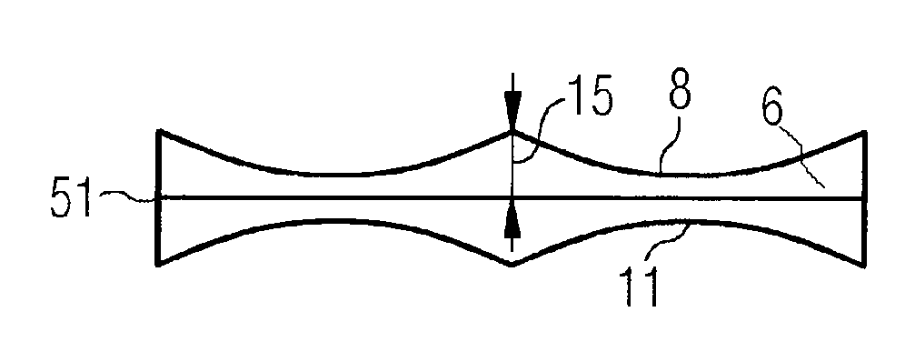
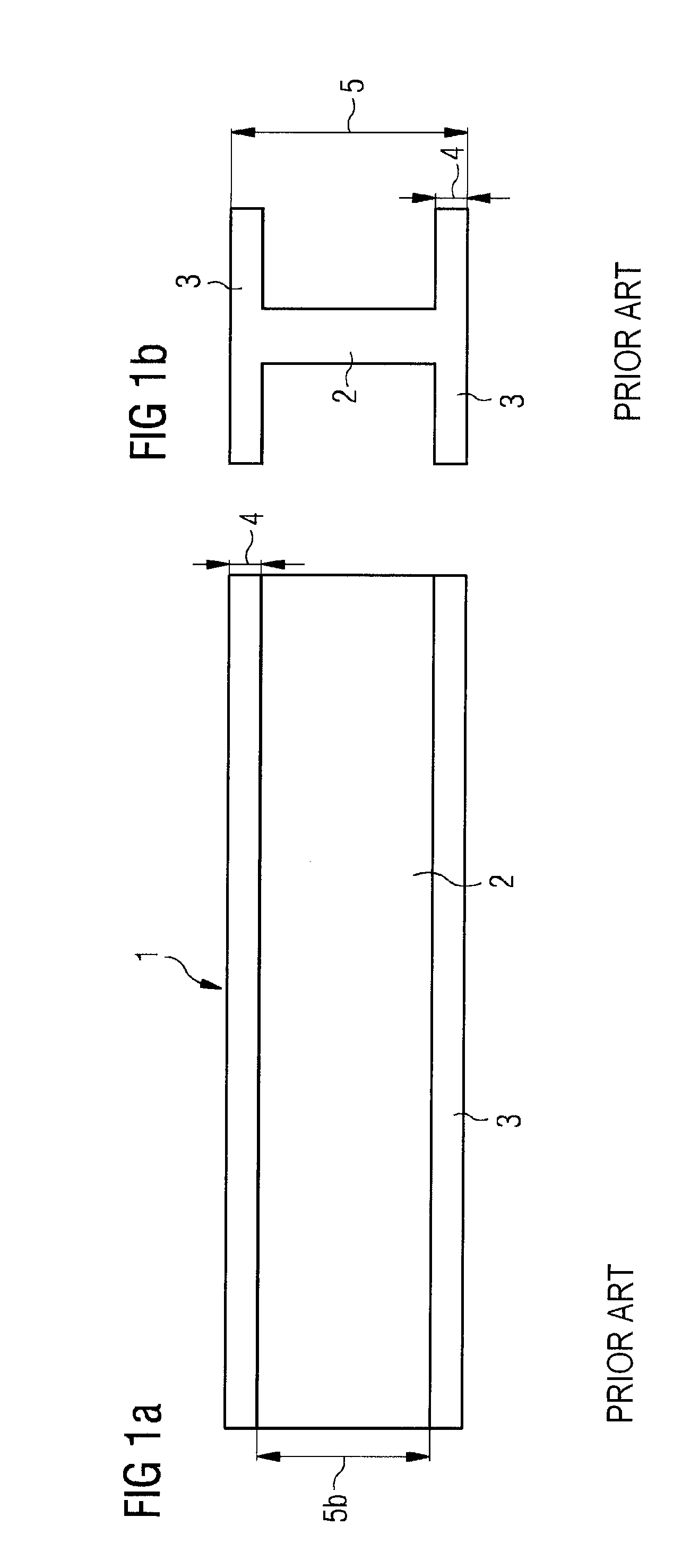
[0032]In a conventional universal beam as illustrated in FIGS. 1a and 1b, the beam 1 has an elongate web 2 and transverse flanges 3 at each elongate edge at the top and bottom of the web. As can be seen from FIG. 1b, the thickness 4 of the flanges along their entire lengths, the depth 5b of the web 2, i.e. its height between its flanges 3 in FIGS. 1a and 1b and the depth 5 of the beam, i.e. the height of the beam including its thickness of its flanges 3 is constant along the length of the beam. Since the cross section is constant and must meet the maximum load requirements along the length of the beam, then at those points along the length at which the maximum loading is not experienced there is more material than is actually required.

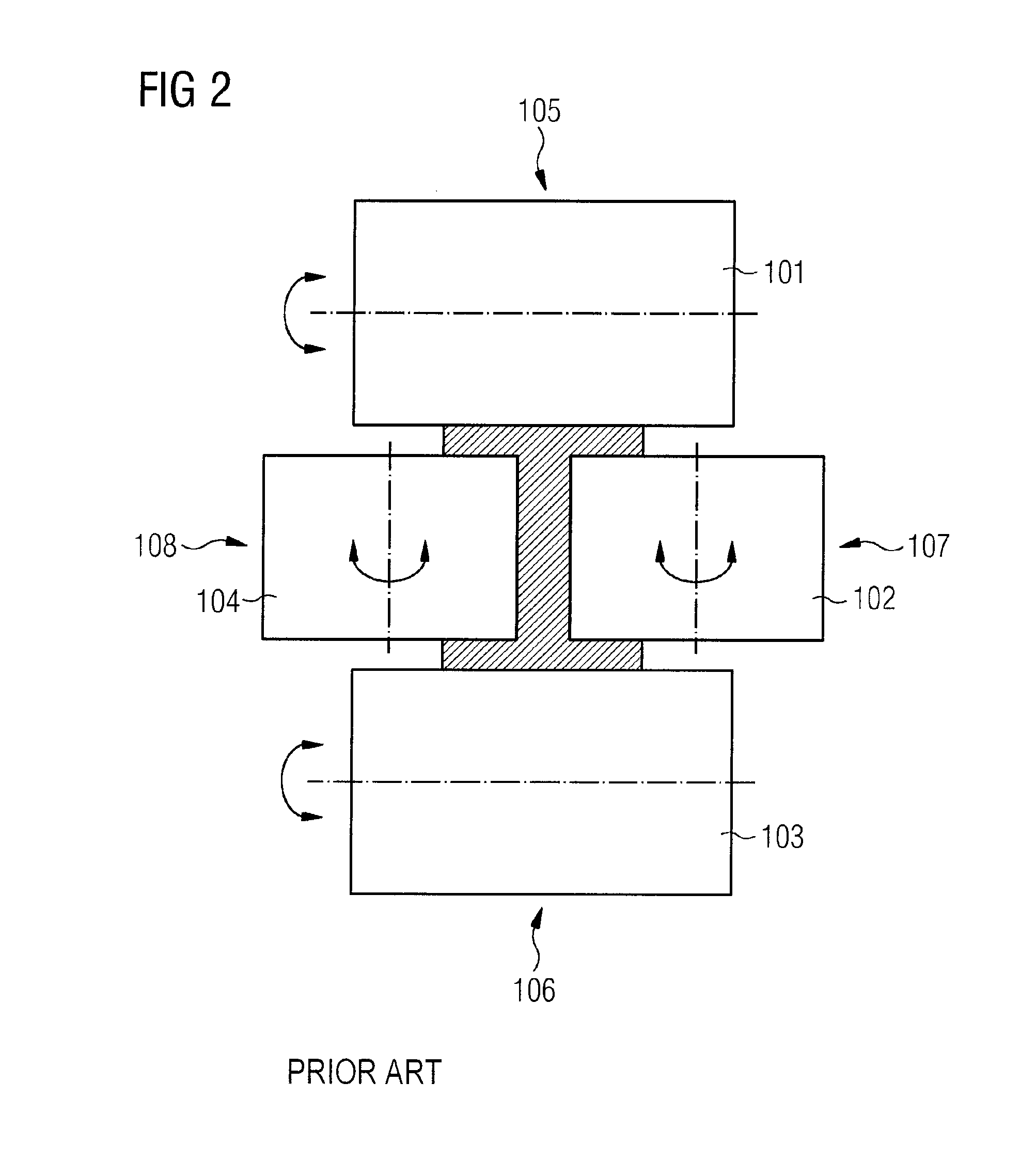
[0033]FIG. 2 illustrates the final rolling step in a conventional universal beam mill in which rolls 101, 103 roll the flanges by exerting a roll force 105, 106, whilst rolls 102, 104 roll the web by exerting a roll force 107, 108. In practice, univers...


PUM

PropertyMeasurementUnit
thicknessaaaaaaaaaa
shapeaaaaaaaaaa
depthaaaaaaaaaa

Abstract

A method of manufacturing a beam comprises rolling, in a longitudinally profiled rolling process, two flange pieces (6,7), such that one surface (8) of each rolled flange piece is profiled according to a predetermined thickness profile; and joining (12,13) the rolled flange pieces together via a web of the beam or by profiled surfaces of the flanges.

Description

CROSS-REFERENCE TO RELATED APPLICATIONS[0001]The present application is a 35 U.S.C. §§371 national phase conversion of PCT / EP2014 / 050365, filed Jan. 10, 2014, which claims priority of Great Britain Patent Application No. 1302281.9, filed Feb. 8, 2013, the contents of which are incorporated by reference herein. The PCT International Application was published in the English language.TECHNICAL FIELD[0002]This invention relates to a method of manufacturing a beam, in particular for structural metal beams.TECHNICAL BACKGROUND[0003]Universal beams also known as I-beams or H-beams are regularly used in building structures. However, the type of beam that is commonly used is not as efficient or optimised as it could be. Typically, the beams are of constant cross section along their length. The size of cross section is selected from a list of catalogue sizes and chosen based on the maximum bending moments and shear forces expected in use. There may be additional criteria such as buckling limi...

Claims


Application Information

Patent Timeline
Patent Type & Authority Applications(United States)
IPC IPC(8): B21B1/092E04C3/06
CPCB21B1/08B21B1/092E04C3/06B21B2001/383B21B2015/0021E04C2003/0421B21B2261/10E04C2003/0413E04C2003/0452B21B2261/043B21B2205/02B21B1/088
Inventor CHAMPION, NICHOLASSTEEPER, MICHAELTAGGART, THOMAS
Owner PRIMETALS TECH
Why Eureka
Try Eureka