Three-phase electric water boiler final-stage control protection device

A technology for control and protection of electric water boilers, applied in the field of final control and protection devices for three-phase electric water boilers, can solve problems such as aging connection lines, high working current, burns, etc., and achieve the effect of preventing accidents and maintaining a safe and silent protection state

Active Publication Date: 2019-07-30
上海富淙环保科技有限公司
View PDF1 Cites 0 Cited by
  • Summary
  • Abstract
  • Description
  • Claims
  • Application Information

AI Technical Summary

Problems solved by technology

The power of the electric heating tube ranges from 2kW to 12kW, and the working current is large. Once the contacts of the relay are stuck, the temperature of the water boiler will inevitably lose control. Although the CPU has issued an instruction to stop heating, the stuck relay will allow the electric heating tube to continue to work. If it is a sealed water tank, there is a danger of explosion. Even if the water tank with a steam exhaust pipe does not explode, a large amount of steam will leak out and cause burns.
In addition, through the fault analysis of "spontaneous combustion" commercial water boilers, we found that the main culprit for the "spontaneous combustion" of these water boilers is the aging or poor contact of the connection line between the relay control board and the electric heating tube. Once the circuit is aging or the contact is poor, a strong electric arc and electric spark will be enough to cause the water boiler to ignite spontaneously and cause a fire accident.

Method used


Image

  • Three-phase electric water boiler final-stage control protection device
  • Three-phase electric water boiler final-stage control protection device
  • Three-phase electric water boiler final-stage control protection device

Examples


Embodiment Construction

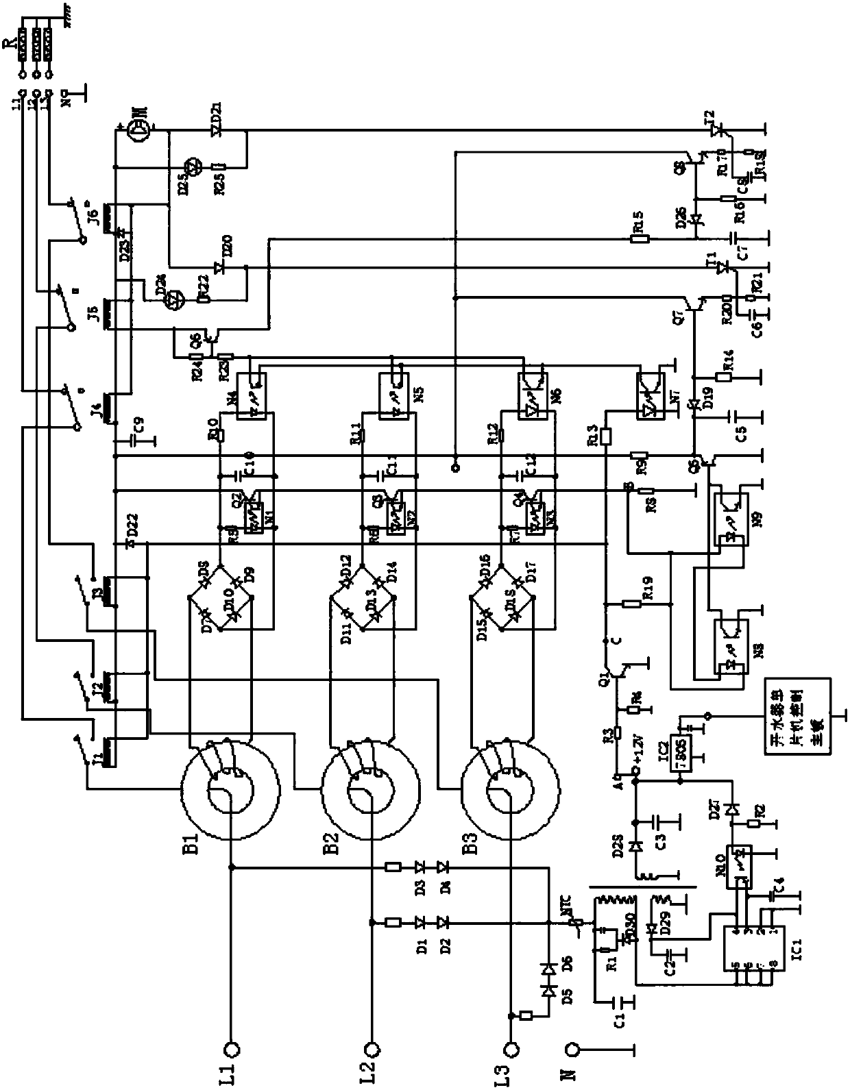
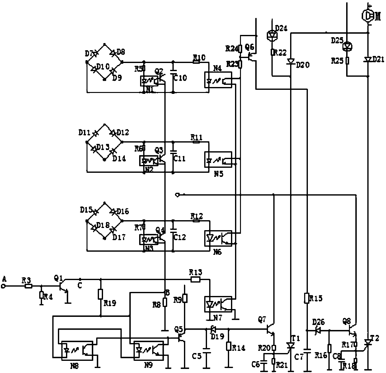
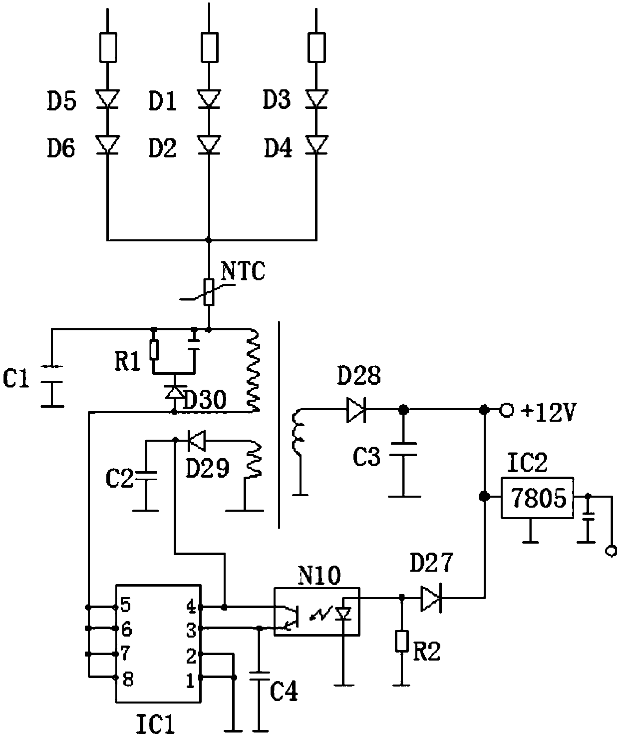
[0012] The specific implementation manners of the present invention will be further described below in conjunction with the drawings and examples.

[0013] Such as Figure 1-3 As shown, a final control and protection device for a three-phase electric water boiler includes an electric heating tube R of the water boiler, working relays J1, J2, J3, protection relays J4, J5, J6, mutual inductors L1, L2, L3, and a protection circuit. It is characterized in that: one end of the electric heating tube R of the water boiler is connected to the zero line of the power supply, and the other end is connected in parallel with three wires, and each wire is respectively provided with working relays J1, J2, J3 and protection relays J4, J5, J6, The protective relays J4, J5, J6 are arranged on one side close to the electric heating tube R, and the other side of the protective relays J4, J5, J6 are connected with working relays J1, J2, J3, and the working relays J1, J2, J3 The wires at the other...


PUM


Abstract

The invention discloses a three-phase electric water boiler final-stage control protection device. The three-phase electric water boiler final-stage control protection device comprises working relaysand protection relays; one end of an electric heating tube of the water boiler is connected with the null line of a power supply, and the other end of the electric heating tube is connected with threewires in parallel; each wire is provided with a working relay and a protection relay, wherein the protection relay is arranged on one side close to the electric heating tube, and the other side of the protection relay is connected with the corresponding working relay; the wire at the other end of the working relay is wound on the primary side of a mutual inductor and then is connected with the three phase line ends of a three-phase alternating current separately; the secondary side of a mutual inductor on each live wire is connected with a protection circuit through a winding wire; the threephase line ends of the three-phase alternating current are connected with a power supply circuit, and the current output end of the power supply circuit is connected with the input end of the protection circuit; and the current output end of the power supply circuit is further connected with a water boiler single-chip microcomputer control mainboard. According to the protection device disclosed bythe invention, any phase line of the input or output of a three-phase protector can be disconnected for performing protection action reliably, so that accidents are completely eradicated.

Description

technical field [0001] The invention relates to a protection device for a water boiler, in particular to a final stage control and protection device for a three-phase electric water boiler. Background technique [0002] At present, household and commercial water boilers are very popular. Most of the control circuits use microcomputer single-chip intelligent control chips in the front stage. This part is relatively mature and stable, and the latter stage uses relays or AC contactors to connect to high-power electric heating tubes. The power of the electric heating tube ranges from 2kW to 12kW, and the working current is large. Once the contacts of the relay are stuck, the temperature of the water boiler will inevitably lose control. Although the CPU has issued an instruction to stop heating, the stuck relay will allow the electric heating tube to continue to work. If it is a sealed water tank, there is a danger of explosion. Even if a water tank with a steam exhaust pipe does...

Claims


Application Information

Patent Timeline
Patent Type & Authority Applications(China)
IPC IPC(8): H02H3/253
CPCH02H3/253
Inventor 黄志军
Owner 上海富淙环保科技有限公司
Why Eureka
Try Eureka