Motor rotor magnetic steel gluing assembly hand and system

A motor rotor and gluing technology, which is applied in electromechanical devices, manufacturing motor generators, manufacturing stator/rotor bodies, etc., can solve the problems of difficult insertion of glue needles, difficult control, and high labor intensity for manual insertion of magnetic steel sheets. To achieve the effect of automatic operation and high efficiency

Pending Publication Date: 2019-07-30
桃子机器人(深圳)有限公司
View PDF0 Cites 1 Cited by
  • Summary
  • Abstract
  • Description
  • Claims
  • Application Information

AI Technical Summary

Problems solved by technology

[0003] At present, in the field of motor manufacturing, most of the manual or transmission dispensing equipment is used to dispens the motor rotor, and the magnetic steel is assembled manually. The traditional dispensing equipment is less efficient for dispensing multi-magnetic poles, and the glue needle is not easy to insert. In deep magnetic poles, the precision of inserting the magnetic steel sheet is high, which is difficult to control, and the labor intensity of the manual insertion of the magnetic steel sheet is high

Method used


Image

  • Motor rotor magnetic steel gluing assembly hand and system
  • Motor rotor magnetic steel gluing assembly hand and system
  • Motor rotor magnetic steel gluing assembly hand and system

Examples


Embodiment 1

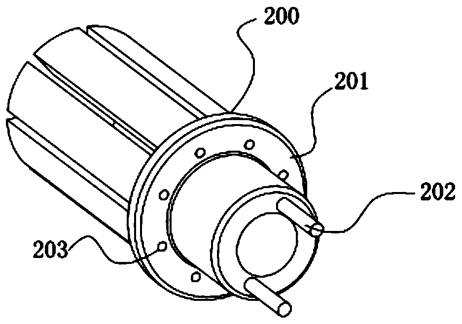
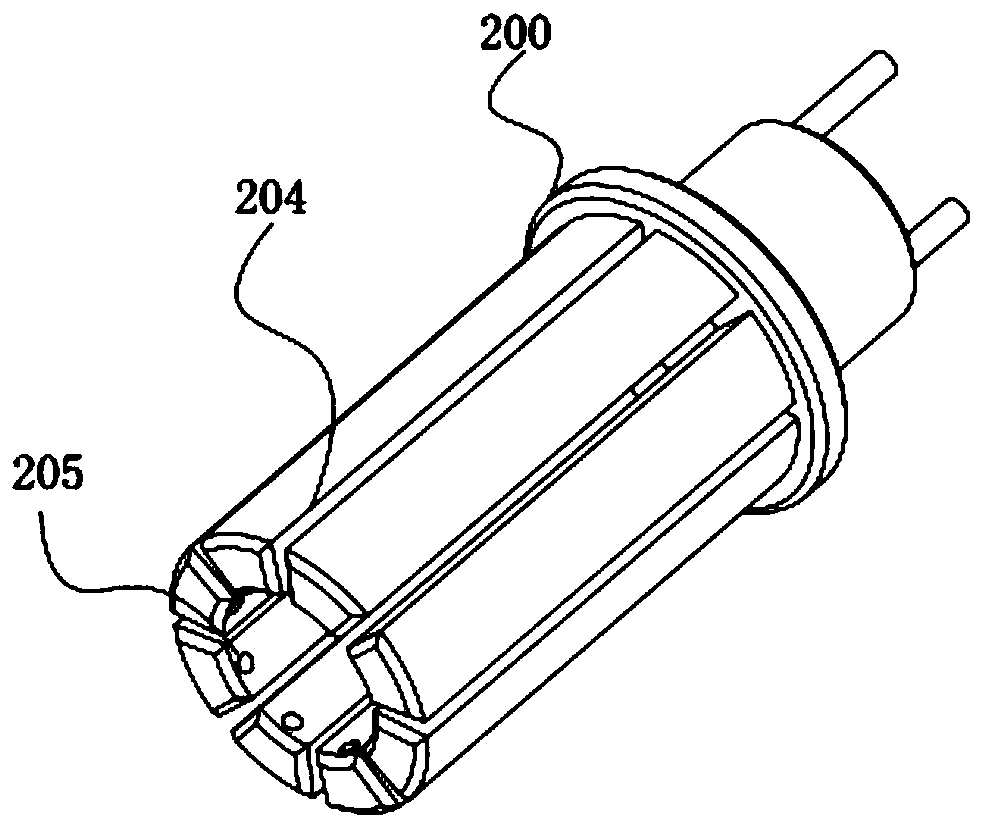
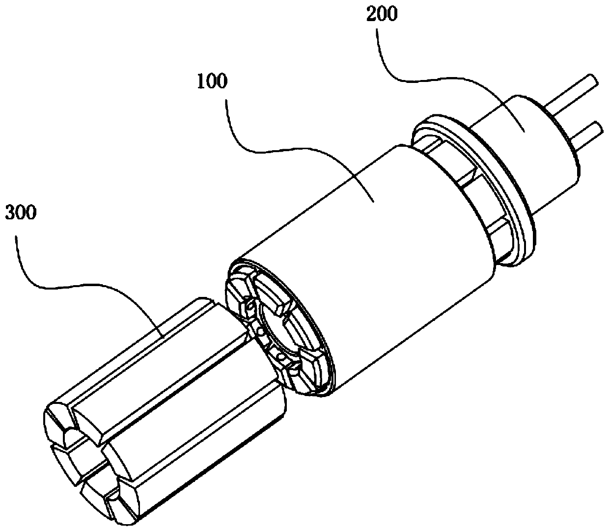
[0021] see Figure 1~4 , in the embodiment of the present invention, a motor rotor magnetic steel gluing assembly hand includes a gluing assembly mechanism 200, specifically, the gluing assembly mechanism 200 includes a sol disk 201 and a glue injection sheet 204, here, the A plurality of injection sheets 204 are installed on the sol tray 201, and the sol tray 201 is provided with an injection hole 203 corresponding to each of the injection sheets 204. Of course, the injection sheets 204 and the magnetic steel sheets 300 are profiled and the injection sheets 204 It can be attracted with the magnetic steel sheet 300 by magnetic force, and the number and arrangement position of the injection film 204 need to be consistent with the magnetic steel sheet 300 to be assembled and fixed, so that the film injection sheet 204 can be inserted into the magnetic steel sheet installation hole in the rotor 100 , under normal circumstances, the magnetic steel sheet 300 is pasted on the outsid...

Embodiment 2

[0026] In an embodiment of the present invention, a motor rotor magnet gluing assembly system includes the motor rotor magnet gluing assembly hand as described in Embodiment 1, and in this system, it can be designed to drive the motor rotor gluing assembly The moving mechanism of the hand is used to realize the automatic movement of the motor rotor magnetic steel gluing assembly hand to achieve efficient magnetic steel assembly.

[0027] It should be noted that, in this technical solution, the gluing assembly mechanism 200 that fits with the rotor and the magnetic steel sheet can be used to perform gluing assembly of multiple magnetic steel sheets 300 at one time, with high efficiency, and the electrodes or magnetic poles It can be controlled to realize automatic operation.


PUM


Abstract

The invention discloses a motor rotor magnetic steel gluing assembly hand and a system, and relates to the technical field of motor assembly. A gluing assembly mechanism is provided, and comprises a sol disc and film injection sheets. A plurality of glue injection sheets are disposed on the sol disc, and glue injection holes corresponding to each of the glue injection sheets are disposed in the sol disc, and the glue injection sheets and magnetic steel sheets are attracted by magnetic force. The glue injection sheets are provided with glue injection channels, and each of the glue injection sheets is provided with a glue outlet, which is communicated with the corresponding glue injection hole through the corresponding glue injection channel. The invention is advantageous in that: the gluingassembly mechanism matched with the rotor and the magnetic steel sheets is used, so that the gluing assembly of a plurality of magnetic steel sheets can be carried out at one time, and the efficiencyis high, and electrodes or magnetic poles can be controlled to realize automatic operation.

Description

technical field [0001] The invention relates to the technical field of motor assembly, in particular to a motor rotor magnetic steel glue-coated assembly hand and system. Background technique [0002] A motor, commonly known as a motor, refers to an electromagnetic device that converts or transmits electrical energy according to the law of electromagnetic induction. Its main function is to generate driving torque, and as a power source for electrical appliances or various machinery, it is widely used in industrial production and life. [0003] At present, in the field of motor manufacturing, most of the manual or transmission dispensing equipment is used to dispens the motor rotor, and the magnetic steel is assembled manually. The traditional dispensing equipment is less efficient for dispensing multi-magnetic poles, and the glue needle is not easy to insert. In the deep magnetic poles, the precision of the magnetic steel sheet insertion is high, which is difficult to contr...

Claims


Application Information

Patent Timeline
IPC IPC(8): H02K15/03B05C5/02B05C11/10
CPCH02K15/03B05C5/0208B05C11/1042
Inventor 刘洋何福森陈银辉
Owner 桃子机器人(深圳)有限公司
Why Eureka
Try Eureka