
Bionic sub-soiling shovel with drag-reduction bionic surface

A technology of deep loosening shovel and bionic bulge, which is applied in the field of bionic deep loosening shovel, can solve the problems of high operating cost, reducing the effect of deep loosening operation, and increasing the cost of agricultural operation.

Pending Publication Date: 2019-08-02
JILIN UNIV
View PDF0 Cites 0 Cited by
  • Summary
  • Abstract
  • Description
  • Claims
  • Application Information

AI Technical Summary

Problems solved by technology

[0003] At present, with the in-depth development of subsoiling technology, the problems in subsoiling are also becoming more and more prominent. First, the resistance of subsoiling is too large, resulting in high energy consumption
Since the plowing depth of the subsoiling operation is between 20 and 40 cm, the amount of soil disturbance is relatively large, and the traction resistance of the operation is relatively large, so the operation resistance and energy consumption are relatively large. Traction machinery for traction operations, combined with the current agricultural development status quo, small plots, individual farmer operations, the purchase of high-horsepower tractors will increase the cost of agricultural operations. The soil core is formed at the lower end of the shovel body, which reduces the operation effect of subsoiling

Method used


Image

  • Bionic sub-soiling shovel with drag-reduction bionic surface
  • Bionic sub-soiling shovel with drag-reduction bionic surface
  • Bionic sub-soiling shovel with drag-reduction bionic surface

Examples


Embodiment Construction

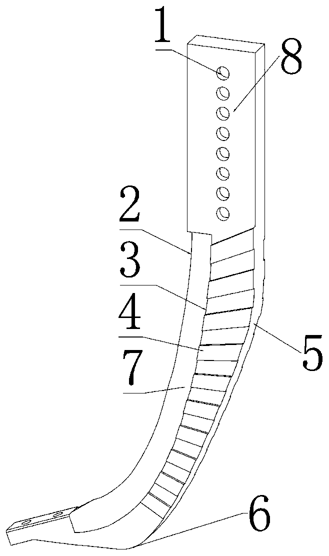
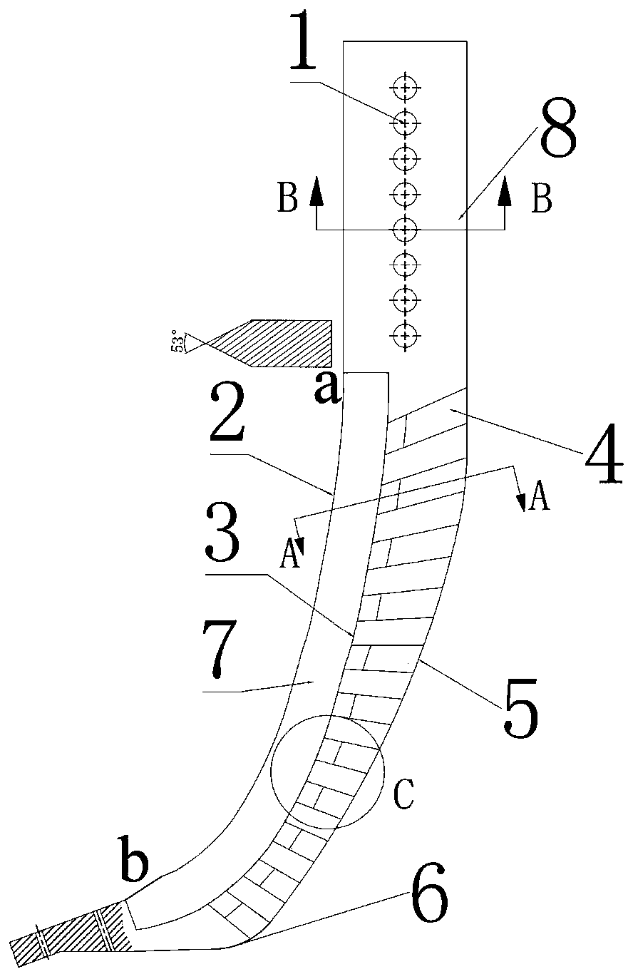
[0022] Such as figure 1 , figure 2 and image 3 As shown, the present invention includes a blind hole 1, an edge front contour line 2, an inner alignment line 3, a bionic raised rib structure 4, a first arc 5, a second arc 6, an edge curved surface 7 and a shovel body 8 ;

[0023] Such as figure 1 and Figure 5 As shown, eight blind holes 1 are arranged at a certain distance on the midline above the shovel body 8, and the aperture is The distance between the center of the blind hole and the left side of the shovel body is 40mm, and the distance from the top surface is 30mm. The distance between the two blind holes is 23mm. The blind hole 1 is fixed on the frame by two bolts for the shovel body. 8 is fixed, the depth of the shovel body is achieved by adjusting and fixing different blind holes 1, the depth of plowing adjustment is 20-45mm, and different depths are selected according to the different soil conditions of the operation.

[0024] Such as figure 2 As shown, ...


PUM

PropertyMeasurementUnit
Widthaaaaaaaaaa

Abstract

The invention provides a bionic sub-soiling shovel with a drag-reduction bionic surface. The bionic sub-soiling shovel comprises blind holes, a cutting edge front outline line, an inner standard line,bionic convex edge strip structures, a first arc line, a second arc line, a cutting edge curved surface and a shovel body, wherein eight blind holes are distributed on the central line at the upper side of the shovel body; the blind holes are fixed on a rack through two bolts and are used for fixing the shovel body; the shovel body is provided with the cutting edge front outline line and the inner standard line; the cutting edge curved surface is formed by a curved surface between the cutting edge front outline line and the inner standard line; the cutting edge front outline line and the inner standard line are front cutting edge curves; the front cutting edge curves are bionic curves; the bionic convex edge strip structures with different heights are distributed on the surface of the shovel body; one side, close to the inner standard line, of each bionic convex edge strip structure is an inclined plane; the bionic convex edge strip structures are symmetrically distributed at two sides of the shovel body; a rear outline line is formed by the first arc line and the second arc line; the two arc lines are tangent. Compared with an international circular-arc-shaped sub-soiling shovel,the bionic sub-soiling shovel provided by the invention has the advantages that the working resistance can be reduced by about 17 percent, the disturbance quantity of soil is reduced, the energy consumption is reduced and the whole quality of the soil is improved.

Description

technical field [0001] The invention relates to the technical field of agricultural machinery, in particular to a bionic deep loosening shovel with a drag-reducing bionic surface. Background technique [0002] As a large agricultural country in my country, the advanced degree of agricultural mechanization determines the quality of agricultural operations, crop growth environment and the quality of later crop growth. However, soil compaction and the upward movement of the plow bottom make the growth of crops restricted, and the root system cannot penetrate below the plow bottom. When there is a lot of rain, the bottom layer of the plow blocks the penetration of rainwater, which will cause rotten roots; when there is little rain, the bottom layer of the plow blocks the rise of water under the layer, causing the crops to die due to lack of water. Subsoiling technology can effectively break the bottom layer of the plow, so that water and nutrients can be fully exchanged, promot...

Claims


Application Information

Patent Timeline
IPC IPC(8): A01B13/08
CPCA01B13/08
Inventor 马云海王立冬吴千端木令坚车军剑吴思阳齐红岩禹江涛陈创发包健伦刘炫廷
Owner JILIN UNIV
Learn More