Chair foot structure

A technology of chair legs and legs, which is applied in the field of chair leg structures, can solve problems such as unstable connection of chair legs, and achieve the effects of saving transportation costs, easy disassembly and assembly, and simple structure

Pending Publication Date: 2019-08-02
黄依群
View PDF1 Cites 0 Cited by
  • Summary
  • Abstract
  • Description
  • Claims
  • Application Information

AI Technical Summary

Problems solved by technology

[0004] The purpose of the present invention is to provide a chair leg structure to solve the problem of unstable connection of the chair legs

Method used


Image

  • Chair foot structure
  • Chair foot structure
  • Chair foot structure

Examples


Embodiment

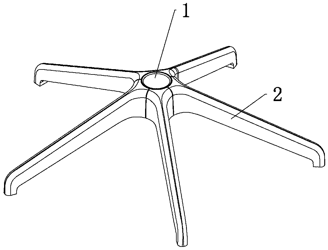
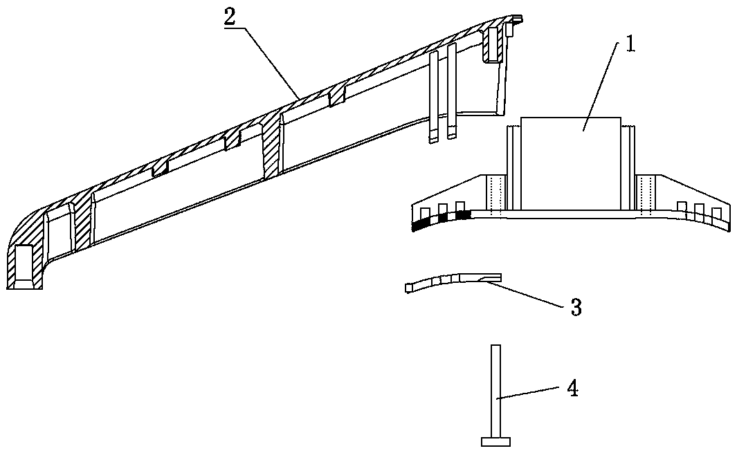
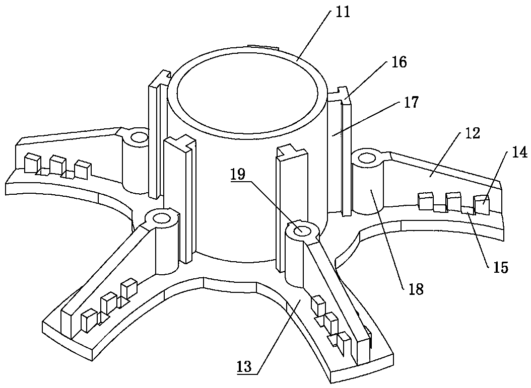
[0028] Example: such as Figure 1 to Figure 5 As shown, a chair foot structure includes a support 1 and a foot 2. The support 1 includes a support body 11 and five installation parts 12 fixed on the support body 11. The five installation parts 12 are evenly distributed on the support body 11. and integrally connected with the supporting body 11. A mounting groove 21 is provided on the leg 2 , and each mounting portion 12 is embedded in the mounting groove 21 of the corresponding leg 2 .

[0029] A support portion 13 for supporting below the support leg 2 is provided below the mounting portion 12 , and a positioning hole 15 axially penetrating is provided on the support portion 13 . A clamping assembly 3 is provided below the supporting part 13 , and an inserting part 22 is provided on the leg 2 , and the inserting part 22 passes through the positioning hole 15 to the bottom of the supporting part 13 and is connected with the clamping assembly 3 . The positioning holes 15 are...


PUM


Abstract

The invention relates to a chair foot structure, which comprises a support element and support feet, wherein the support element comprises a support body and a plurality of installing parts, wherein installing grooves are arranged on the support feet; each installing part is embedded in the installing groove of the corresponding support foot; a support part is arranged under the installing part; aclamping assembly is arranged under the support part; at least one part of the support part passes through the support part and is fixedly connected with the clamping assembly; a fastening assembly is arranged between the support element and the support foot; the fastening assembly sequentially passes through the clamping assembly, the support part and the installing part to be screwed and connected with the support feet. The structure is simple; the mounting and the dismounting are simple and convenient; the transportation cost is reduced; the connection between the support feet and the support element is stable and firm; the fixing and position limiting structures are used in the transverse and longitudinal directions; falling and swinging cannot easily occur; the support feet and the support elements are connected in the axial direction through the fastening assembly, and are also connected with the clamping assembly through an insertion and connecting part; the two-point connection is realized in the radial direction; the connection pressure of the fastening assembly is reduced, so that the connection is more stable and firmer.

Description

technical field [0001] The invention relates to the technical field of chair legs, in particular to a chair leg structure. Background technique [0002] Existing chair legs are usually integrally formed plastic parts or metal parts, but the integrally formed chair legs have the problem of difficulty in processing. Due to the large volume and complex structure of the chair legs, the injection molding, casting molding and other processes take a long time, the mechanical cold processing process is complicated, and the production efficiency is low. In addition, since the chair legs take up a large space, the cost of packaging and transportation is relatively high. [0003] For example: the Chinese utility model patent with the application number 201020672820.2 discloses a chair foot that can be easily disassembled and assembled, including a steam pressure rod support block and at least 3 toes. The steam pressure rod support block is used to support the steam pressure rod of the...

Claims


Application Information

Patent Timeline
Patent Type & Authority Applications(China)
IPC IPC(8): A47C7/00F16B12/10
CPCA47C7/004F16B12/10F16B2012/106
Inventor 黄依群
Owner 黄依群
Why Eureka
Try Eureka