Pipe fitting connection rapid clamping device and application method thereof

A technology for clamping devices and pipe fittings, which is applied in the direction of auxiliary devices, welding equipment, auxiliary welding equipment, etc., can solve the problems of inflexible pipe welding processing operations and inability to freely rotate pipe fittings, and achieve stable adjustment and high operating efficiency.

Active Publication Date: 2019-08-02
ZHEJIANG BANNINGER PIPING SYST LTD
View PDF7 Cites 8 Cited by
  • Summary
  • Abstract
  • Description
  • Claims
  • Application Information

AI Technical Summary

Problems solved by technology

[0003] However, the existing fixing fixtures for welding can only be adapted to pipe fittings of corresponding specifications, and can only be used to process welded pipe fittings in the factory, and cannot be used to quickly weld pipe fittings in a hand-held manner on site. At the same time, when fixing pipe fittings for welding processing, Unable to freely rotate the pipe fittings, resulting in inflexible pipe fitting welding operations

Method used


Image

  • Pipe fitting connection rapid clamping device and application method thereof
  • Pipe fitting connection rapid clamping device and application method thereof
  • Pipe fitting connection rapid clamping device and application method thereof

Examples


Embodiment Construction

[0041] The following are specific embodiments of the present invention and in conjunction with the accompanying drawings, the technical solutions of the present invention are further described, but the present invention is not limited to these embodiments.

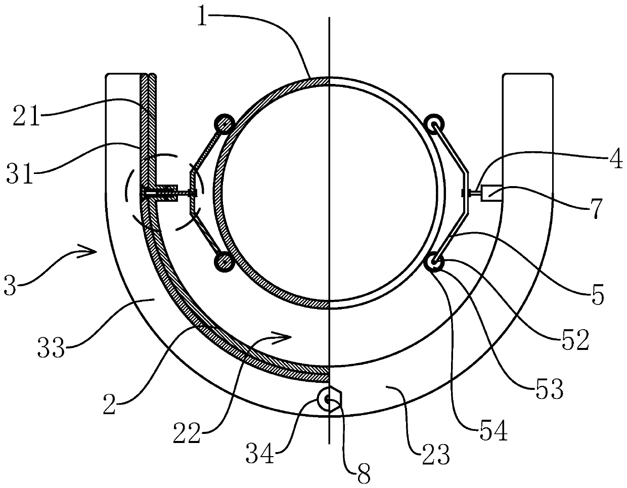
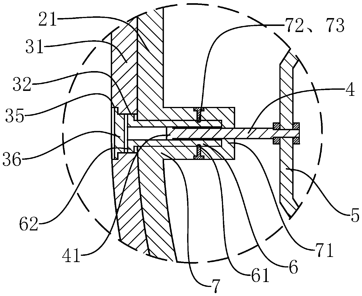
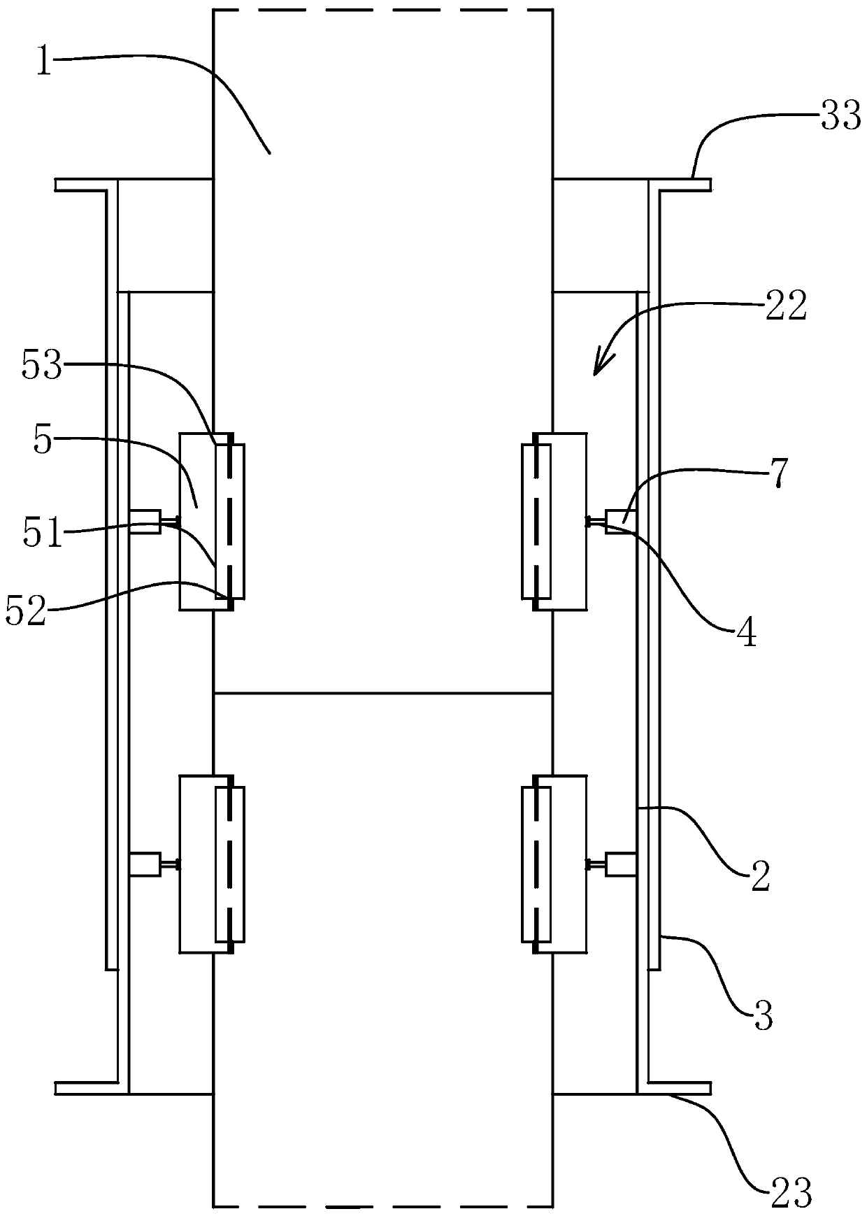
[0042] Such as Figure 1-4As shown, the present invention is a quick clamping device for connecting pipe fittings, which is used for clamping two round tubular pipe fittings 1 to be connected. There are two inner seat plates 21 parallel to each other on the support 2, and two outer seat plates 31 parallel to each other are provided on the outer support 3, and the opposite inner surfaces of the two outer seat plates 31 are respectively connected to the two inner seat plates 21. The opposite outer sides slide and fit together, and the inner support 2 has a slotted clamping groove 22 whose length direction is parallel to the inner seat plate 21. It also includes four clamping mechanisms, and two of them form a group. And one...


PUM


Abstract

The invention provides a pipe fitting connection rapid clamping device and an application method thereof, and belongs to the field of pipe fittings. The problem that existing welding clamps cannot beused for field construction is solved. The pipe fitting connection rapid clamping device is used for clamping pipe fittings. The clamping device comprises an inner support and an outer support. Two inner support plates are arranged on the inner support, and two outer support plates are arranged on the outer support. The clamping device further comprises clamping mechanisms. The clamping mechanismscomprise adjusting rods and elastic sheets. Rolling wheels connected with the elastic sheets through rotating shafts are further included. The clamping mechanisms further comprise locating pipes. Sleeve pipe holes are formed in the locating pipes. Locating rings are arranged at the front ends of the locating pipes. Locating holes are formed in the locating rings. Adjusting pipes arranged in the sleeve pipe holes in a penetrating manner are further included. Screw blocks are fixed to the rear ends of the adjusting rods. Sliding grooves are formed in the outer walls of the adjusting pipes. Sliding blocks are arranged on the inner walls of the locating pipes. Gears are fixed to the outer walls of the rear ends of the adjusting pipes. Adjusting grooves are formed in the inner side faces of the outer support plates. Toothed grooves are formed in the groove walls of the adjusting grooves. The clamping device is suitable for rapidly clamping and locating two pipe fittings of different specifications on site for construction.

Description

technical field [0001] The invention belongs to the technical field of pipe fittings, and relates to a fast clamping device for connecting pipe fittings and a use method thereof. Background technique [0002] When welding metal materials, it is necessary to use clamps to fix the metal materials, and then operate the welding machine to weld the metal materials. For the welding of pipe fittings, it is necessary to rotate the pipe fittings one circle to complete the welding. [0003] However, the existing fixing fixtures for welding can only be adapted to pipe fittings of corresponding specifications, and can only be used to process welded pipe fittings in the factory, and cannot be used to quickly weld pipe fittings in a hand-held manner on site. At the same time, when fixing pipe fittings for welding processing, The pipe fittings cannot be rotated freely, resulting in inflexible welding operation of the pipe fittings. Contents of the invention [0004] The purpose of the ...

Claims


Application Information

Patent Timeline
Patent Type & Authority Applications(China)
IPC IPC(8): B23K37/053
CPCB23K37/053B23K37/0533
Inventor 黄士玉
Owner ZHEJIANG BANNINGER PIPING SYST LTD
Why Eureka
Try Eureka