A rapid manufacturing method and manufacturing auxiliary system for a composite material structural plate

A composite material and manufacturing method technology, applied in the directions of lamination auxiliary operations, chemical instruments and methods, computer-aided design, etc., can solve the problems of difficult product inspection, low production efficiency, high labor intensity, etc., to avoid manual measurement and marking. , improve efficiency and accuracy, improve the effect of inspection efficiency

Active Publication Date: 2021-02-12
BEIJING INST OF SPACECRAFT SYST ENG
View PDF13 Cites 0 Cited by
  • Summary
  • Abstract
  • Description
  • Claims
  • Application Information

AI Technical Summary

Problems solved by technology

There are many deficiencies in the current production mode, and it is increasingly unable to meet the requirements of efficiency and progress; in order to meet the production expansion needs of structural panels, the development mode of structural panels must be optimized
After upgrading the 2D drawing of the structural plate to the 3D model, the process preparation efficiency has more than doubled; however, there is a problem of insufficient means in the placement of structural embedded parts based on the 3D model: due to the irreducible distance between the computer and the workbench , after the on-site workers use the computer to view the 3D model of the structural slab, such as figure 1 As shown, workers need to manually record or mentally record the type and position of the structural embedded parts, and place the embedded parts according to the records or memories; in addition, due to the distance between the computer and the workbench, workers need to be between the computer and the workbench. Walk back and forth between the stations, repeatedly confirm the model information and physical objects, and ensure that the embedded parts are placed correctly, the thermal control measures are in the correct area, and the position is correct
In this production mode, there have been problems such as high labor intensity of on-site workers, low production efficiency, low first-time success rate of products, and difficult product inspection.

Method used


Image

  • A rapid manufacturing method and manufacturing auxiliary system for a composite material structural plate
  • A rapid manufacturing method and manufacturing auxiliary system for a composite material structural plate
  • A rapid manufacturing method and manufacturing auxiliary system for a composite material structural plate

Examples


Embodiment Construction

[0039] The present invention will be described in detail below with reference to the accompanying drawings and examples.

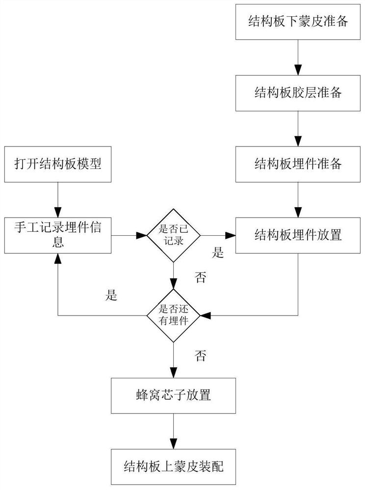
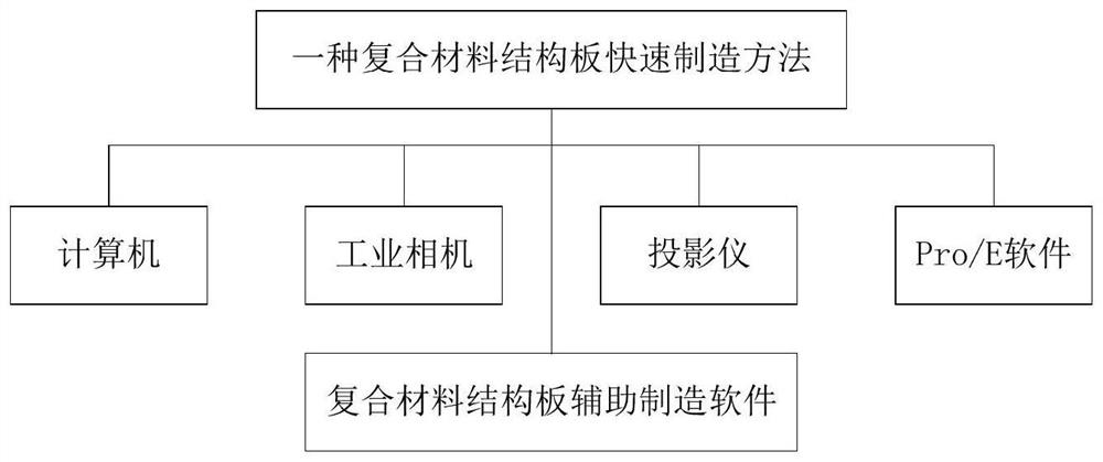
[0040] This embodiment provides a method for rapid manufacturing of composite material structural panels, such as figure 2 As shown, the hardware and software are used. The hardware includes computers, calibration boards, industrial cameras and projectors, and the main software uses Pro / E.

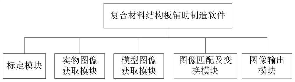
[0041] The computer at the production site is used for the display of the composite material structural plate model, software operation and hardware connection, and Pro / E secondary development composite material structural plate auxiliary manufacturing software is configured, and it is connected with industrial cameras and projectors in place.

[0042] The industrial camera is used to obtain the physical image information of the structural plate under the skin and the target on the field workbench, and use image recognition to process the physical image.

[0043] The...


PUM


Abstract

The invention discloses a rapid manufacturing method of a composite material structural plate and a manufacturing auxiliary system. With the help of the manufacturing auxiliary system, through the acquisition of the actual image of the skin under the structural plate, the acquisition of the image of the structural plate model, and image matching and transformation, the image of the structural plate model is passed through The projector is projected onto the surface of the lower skin, and then the embedded parts, the honeycomb core and the skin on the structural plate are assembled in sequence. The invention can simplify on-site workers' acquisition of assembly information, and greatly improves production efficiency, accuracy and first-time success rate.

Description

technical field [0001] The invention relates to the technical field of composite material structural panels, in particular to a rapid manufacturing method of composite material structural panels and a manufacturing auxiliary system. Background technique [0002] The composite material structural panel is composed of upper and lower skins, honeycomb core, and embedded parts. The skin is located on the outermost side of the structural panel; Structural slabs inside the honeycomb core for connecting external objects to structural slabs. Composite structural plates have the characteristics of high strength and low density, and are widely used in the field of spacecraft development. [0003] Usually, spacecrafts have different configurations, different layouts, and are developed in one piece, resulting in different structural panels and one-piece production. The skin of the composite structural plate is cut and drilled by machine, but the honeycomb core and embedded parts need ...

Claims


Application Information

Patent Timeline
Patent Type & Authority Patents(China)
IPC IPC(8): B32B37/14B32B37/12B32B38/18G06T7/80G06F30/15G06F30/20G06F113/26
CPCB32B37/146B32B37/1284B32B38/1833G06T7/80G06T2207/30208G06F30/00
Inventor 周孝伦刘金山罗成周占伟王黎黎陈海峰尉世厚郝刚刚朱位杨春梁翠娜薛宏伟嵇景全谭沧海王腾
Owner BEIJING INST OF SPACECRAFT SYST ENG
Why Eureka
Try Eureka