Integral motor of novel clutch transmission mechanism

A clutch transmission, integrated technology, applied in the field of washing machines, can solve the problems of no outstanding improvement in planetary gear transmission, increase in the probability of bearing failure, increase the cost of the whole machine, etc., achieve high reliability and transmission efficiency, reduce design The effect of high manufacturing cost and high stability

Active Publication Date: 2019-08-02
芜湖卧龙家用电机有限公司 +1
View PDF9 Cites 4 Cited by
  • Summary
  • Abstract
  • Description
  • Claims
  • Application Information

AI Technical Summary

Problems solved by technology

However, most of the technical innovations are limited to specific modifications on the traditional deceleration clutch. As stated in CN104878564 B, the author only innovates the clutch part and the clutch control part, although some innovations have been made in the form of an integrated motor , but except for the clutch part, it is only aimed at the simple function superposition of the motor and the deceleration clutch, and has not made substantial improvements to the important part of the deceleration transmission chain; as stated in CN 104631031 B, the author has a high degree of innovation in the clutch part, but the split The application of bearings is costly, and the second is that the sliding of the inner ring of the split bearing will increase the failure probability of the bearing, and the author has not made outstanding improvements to the traditional planetary gear transmission; the planetary gear transmission has its own inherent advantages, stable transmission, large traditional ratio, but due to the combination of the sun wheel and the brake wheel, the cost of the whole machine is inevitably increased; as in CN 107287829 A, the brake assembly includes devices such as brake discs, and the number of parts is large , high manufacturing cost

Method used


Image

  • Integral motor of novel clutch transmission mechanism
  • Integral motor of novel clutch transmission mechanism
  • Integral motor of novel clutch transmission mechanism

Examples


Embodiment Construction

[0033] The technical solution of the present invention will be further described in detail below in conjunction with the accompanying drawings.

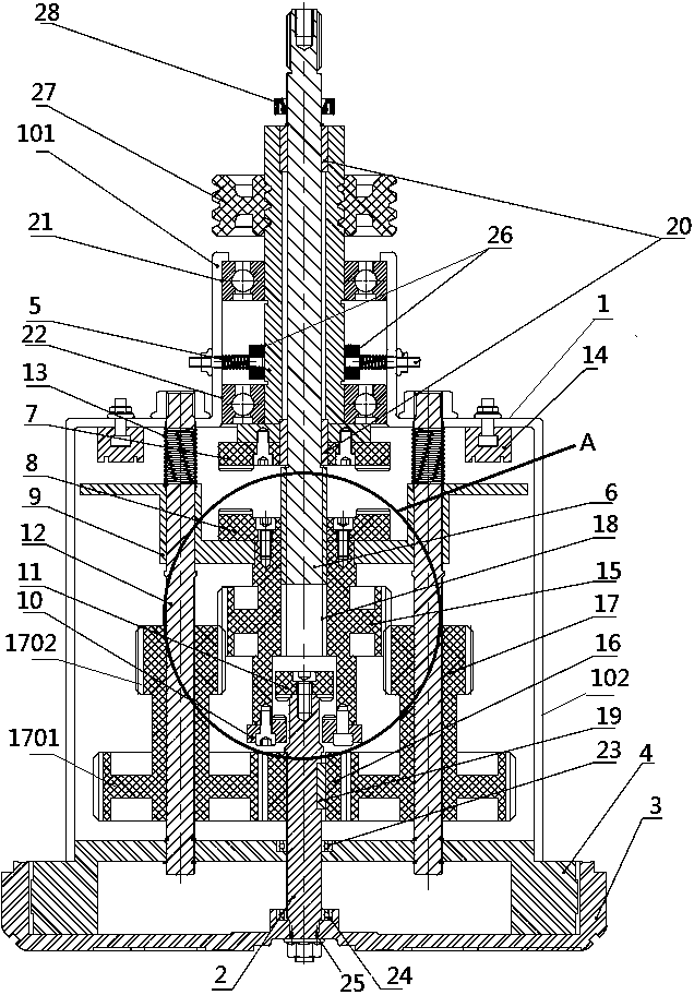
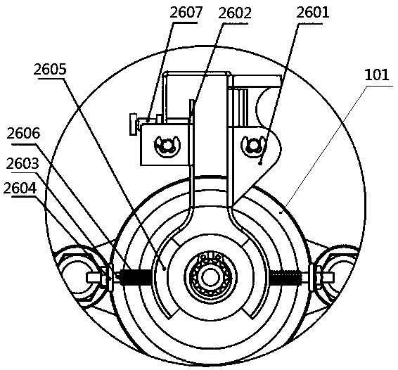
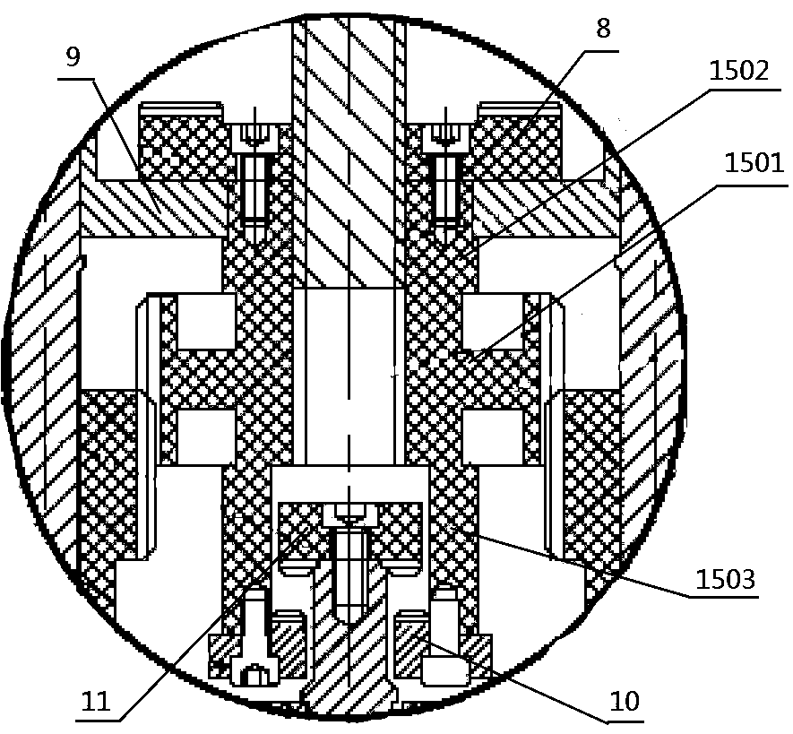
[0034] Such as Figure 1-4 As shown, an integrated motor with a novel clutch transmission structure includes an outer rotor 3 motor assembly, a clutch assembly, a deceleration assembly, a brake 26 and a housing 1, and the outer rotor 3 motor assembly includes an outer rotor 3 with an input shaft 2 and a stator 4. The deceleration assembly includes a deceleration transmission system, a dehydration shaft 5 and a washing shaft 6. The lower end of the housing 1 is connected and fixed to the upper part of the stator 4 to form a closed inner cavity. The clutch assembly and the deceleration assembly are arranged in the inner cavity of the housing 1. The assembly includes an upper clutch disc 7, a lower clutch disc 8 that can engage with the upper clutch disc 7, a supporting plate 9, a movable joint disc 10, a fixed joint disc 11 that can en...


PUM


Abstract

The invention discloses an integral motor of a novel clutch transmission mechanism and relates to the field of washing machines. A conventional washing machine power transmission system is generally of a conventional motor-belt pulley-speed reduction clutch separated structure which is large in space occupation, incompact in structure and low in reliability. The integral motor comprises a stator,a rotor, a brake, a shell, an input shaft, an input gear, a duplicate gear, an output gear, a moveable connecting disc, a fixed connecting disc, an upper clutch disc, a lower clutch disc and an electric flux magnet. When the electric flux magnet is not electrified, input shaft power is subjected to two-stage speed reduction of the input gear, the duplicate gear and the output gear, and a washing shaft is driven to rotate to implement washing; when the electric flux magnet is electrified, the output gear and the duplicate gear are dissociated from meshing, the upper clutch disc is meshed with the lower clutch disc, power is conducted to the output gear from the moveable connecting disc and the fixed connecting disc, a dewatering shaft and the washing shaft are simultaneously driven by the output gear to rotate in a same direction at a high speed, and then dewatering can be achieved. The integral motor is compact in overall structure and high in integration degree.

Description

technical field [0001] The invention relates to the field of washing machines, in particular to an integrated motor with a novel clutch transmission structure. Background technique [0002] At present, along with the raising of people's living standard, washing machine has been widely used. When the washing machine washes and dehydrates the clothes, the traditional pulsator washing machine mainly uses the motor to drive the reducer and clutch parts, and then drives the pulsator to rotate to wash the clothes, and to drive the dehydration bucket to rotate to dehydrate the clothes. The existing washing machine power and transmission system generally adopts the traditional motor-pulley-reduction clutch split structure, which takes up a large space and is not compact in structure; For brake levers, etc., the clutch unit with a square wire spring is used, which has short life, poor durability, and unreliable clutch operation. If it is washed for a long time, the square wire sprin...

Claims


Application Information

Patent Timeline
Patent Type & Authority Applications(China)
IPC IPC(8): D06F37/30
CPCD06F37/304
Inventor 杜荣法叶乾杰陈祥王延刚
Owner 芜湖卧龙家用电机有限公司
Why Eureka
Try Eureka