Hollow anti-slip anti-liquefaction pile

An anti-liquefaction, hollow technology, applied in sheet pile wall, soil protection, construction and other directions, can solve the problems of large amount of engineering, substandard strength, difficult construction, etc., to achieve the effect of easy construction, material saving, convenient transportation

Inactive Publication Date: 2019-08-02
NORTHEASTERN UNIV
View PDF5 Cites 1 Cited by
  • Summary
  • Abstract
  • Description
  • Claims
  • Application Information

AI Technical Summary

Problems solved by technology

[0002] Ordinary reinforced concrete prefabricated piles are divided into solid piles and hollow piles. Although solid piles have high strength and high hardness, they often have problems such as high cost and inconvenient transportation and construction operations; while hollow piles are light and easy to construct. But it will have disadvantages such as weak strength, easy damage and instability
At present, hollow prefabricated reinforced concrete piles with only one circular hole are often used in construction. However, due to the practical limitations of the project, when the cross-sectional area of ​​the pile body is required to be too large, the pile body with only one pile hole cannot be used in the construction process. There will be problems such as high construction difficulty, long time period, and large amount of engineering. Sometimes, the overall strength of the pile body will no longer meet the standard due to the large single hole area, and the soil instability caused by the liquefaction of the soil. It is also a problem that should be improved in the project

Method used


Image

  • Hollow anti-slip anti-liquefaction pile
  • Hollow anti-slip anti-liquefaction pile
  • Hollow anti-slip anti-liquefaction pile

Examples


Embodiment Construction

[0023] It should be noted that all directional indications (such as up, down, left, right, front, back...) in the embodiments of the present invention are only used to explain the relationship between the components in a certain posture (as shown in the accompanying drawings). Relative positional relationship, movement conditions, etc., if the specific posture changes, the directional indication will also change accordingly.

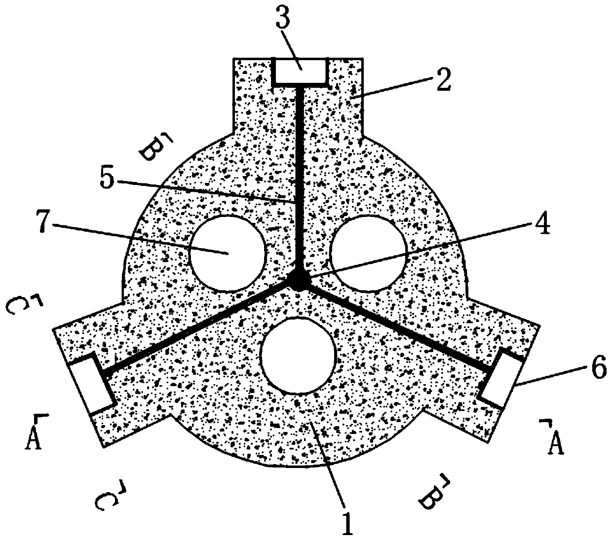
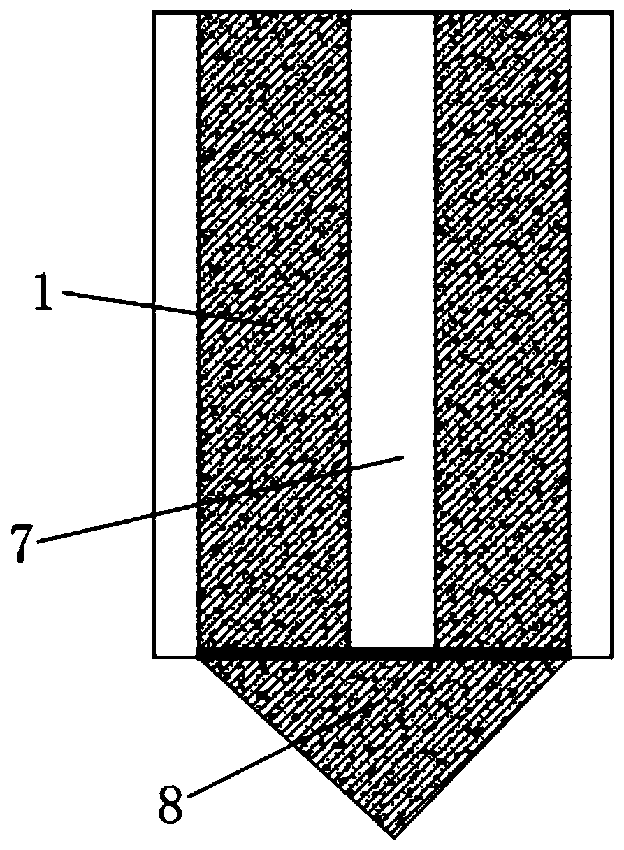
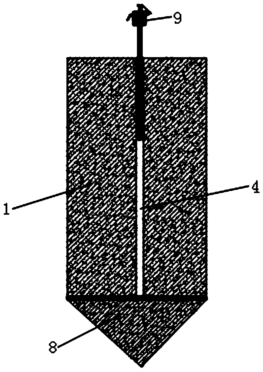
[0024] Such as Figure 1 to Figure 4 As shown, the present invention provides a hollow anti-sliding and anti-liquefaction pile, comprising a pile body 1, a cuboid protrusion 2, a water storage tank 3, a water pumping hole 4, and a water guide hole 5, and several cuboid protrusions 2 are evenly distributed along the periphery of the pile body 1. , in order to play anti-sliding effect, improve the anti-sliding ability and shear resistance level of the soil slope, several cuboid protrusions 2 are respectively provided with water storage tanks 3 outside, sev...


PUM


Abstract

The invention belongs to the technical field of soil body stability research and discloses a hollow anti-slip anti-liquefaction pile, comprising a pile body, cuboid protrusions, a water storage tank,a water pumping hole and water guide holes. A plurality of cuboid protrusions are evenly distributed along the periphery of the pile body. Water storage tanks are respectively formed in the outer sides of the cuboid protrusions, filter screens are arranged on the outer sides of the water storage tanks respectively, the water pumping hole is formed in the center of the pile body, the water storagetanks communicate with the water pumping hole through the water guide holes respectively, a plurality of through hole channels are formed in the pile body, a pile head is fixed to the bottom of the pile body, and the cuboid protrusions, the water storage tanks and the water pumping hole are parallel to a shaft of the pile body. The hollow anti-slip anti-liquefaction pile has the characteristics ofdrainage and liquefaction resistance, the outer sides of the cuboid protrusions on the periphery of the pile body are provided with the water storage tanks, the water storage tanks are covered with the double-layer stainless steel filter screens, so as to prevent the filter screens from being blocked when large-particle-size blocks in soil pass through, and water in the water storage tanks is guided into the water pumping pipe through the water guide holes formed in the pile body and then is pumped out by a water pump in a unified mode.

Description

technical field [0001] The invention belongs to the technical field of soil stability research, and in particular relates to a hollow anti-sliding and anti-liquefaction pile. Background technique [0002] Ordinary reinforced concrete prefabricated piles are divided into solid piles and hollow piles. Although solid piles have high strength and high hardness, they often have problems such as high cost and inconvenient transportation and construction operations; while hollow piles are light and easy to construct. But it will have disadvantages such as weak strength, easy damage and instability. At present, hollow prefabricated reinforced concrete piles with only one circular hole are often used in construction. However, due to the practical limitations of the project, when the cross-sectional area of ​​the pile body is required to be too large, the pile body with only one pile hole cannot be used in the construction process. There will be problems such as high construction dif...

Claims


Application Information

Patent Timeline
Patent Type & Authority Applications(China)
IPC IPC(8): E02D5/30E02D3/10
CPCE02D3/10E02D5/30E02D2200/165
Inventor 王述红孙子涵王鹏宇何坚金长宇
Owner NORTHEASTERN UNIV
Why Eureka
Try Eureka