
A backlight module and display device

A technology of a backlight module and a light guide plate, which is applied in the directions of light guides, optics, and optical components, can solve the problems of bending the bottom 51 of the frame body 50, increasing the thickness of the liquid crystal display, and increasing the thickness of the local area of ​​the backlight module. Improve the effect of increasing thickness, realizing thin design, and reducing height difference

Active Publication Date: 2022-07-29
XIAMEN TIANMA MICRO ELECTRONICS
View PDF7 Cites 0 Cited by
  • Summary
  • Abstract
  • Description
  • Claims
  • Application Information

AI Technical Summary

Problems solved by technology

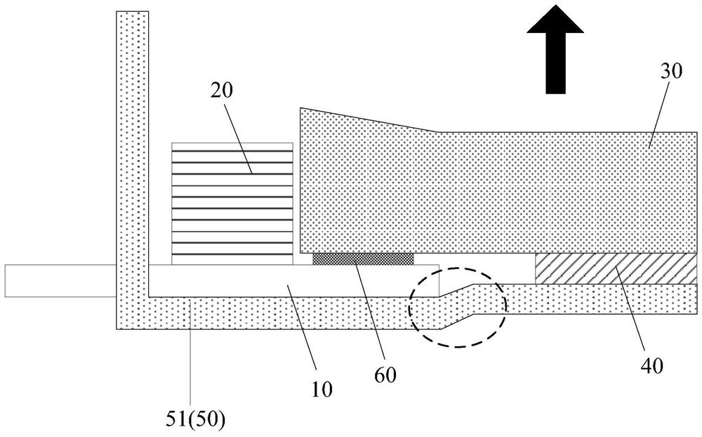
[0003] However, for the backlight module with the above structure, because the thickness of the flexible circuit board 10 is generally the same everywhere, and the fixing glue 60 is generally provided between the flexible circuit board 10 and the light guide plate 30, so that the flexible circuit board 10 and the fixed The sum of the thicknesses of the glue 60 will be greater than the thickness of the reflection sheet 40, causing the bottom 51 of the frame body 50 to bend (as figure 1 The area shown by the dotted circle in the middle), resulting in an increase in the thickness of the local area of ​​​​the backlight module, and eventually leads to an increase in the thickness of the LCD

Method used


Image

  • A backlight module and display device
  • A backlight module and display device
  • A backlight module and display device

Examples


Embodiment Construction

[0025] Specific implementations of a backlight module and a display device provided by embodiments of the present invention will be described in detail below with reference to the accompanying drawings. It should be noted that the described embodiments are only a part of the embodiments of the present invention, but not all of the embodiments. Based on the embodiments of the present invention, all other embodiments obtained by those of ordinary skill in the art without creative efforts shall fall within the protection scope of the present invention.

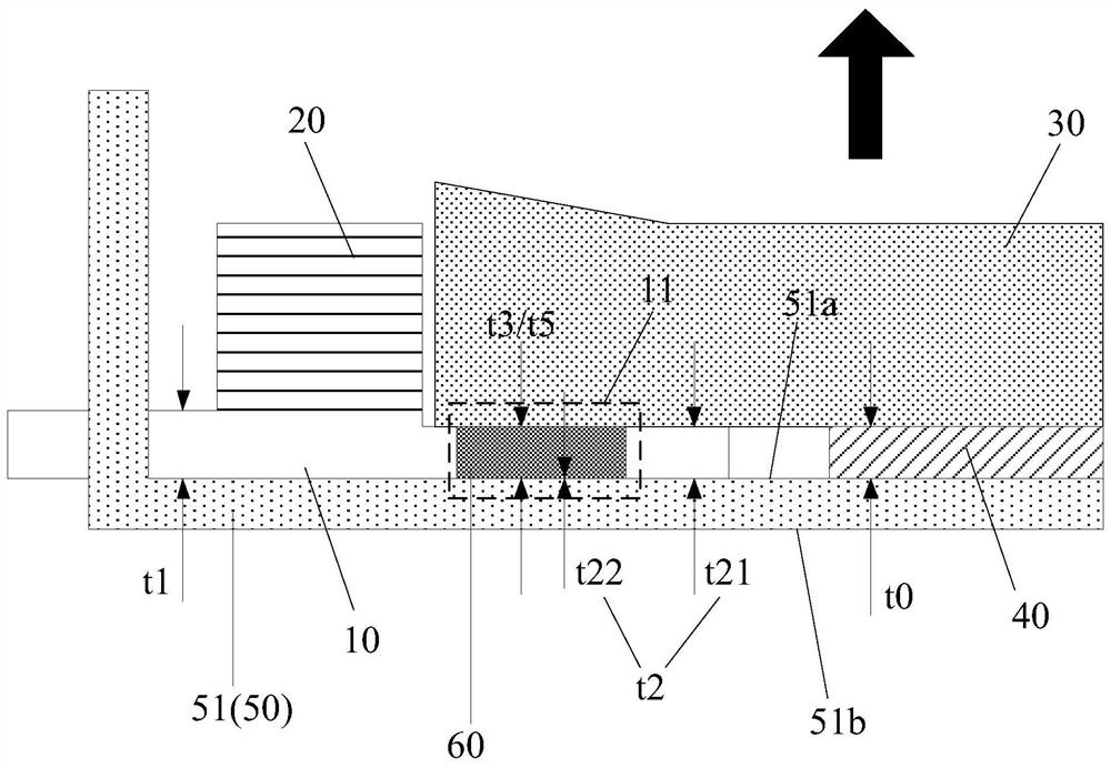
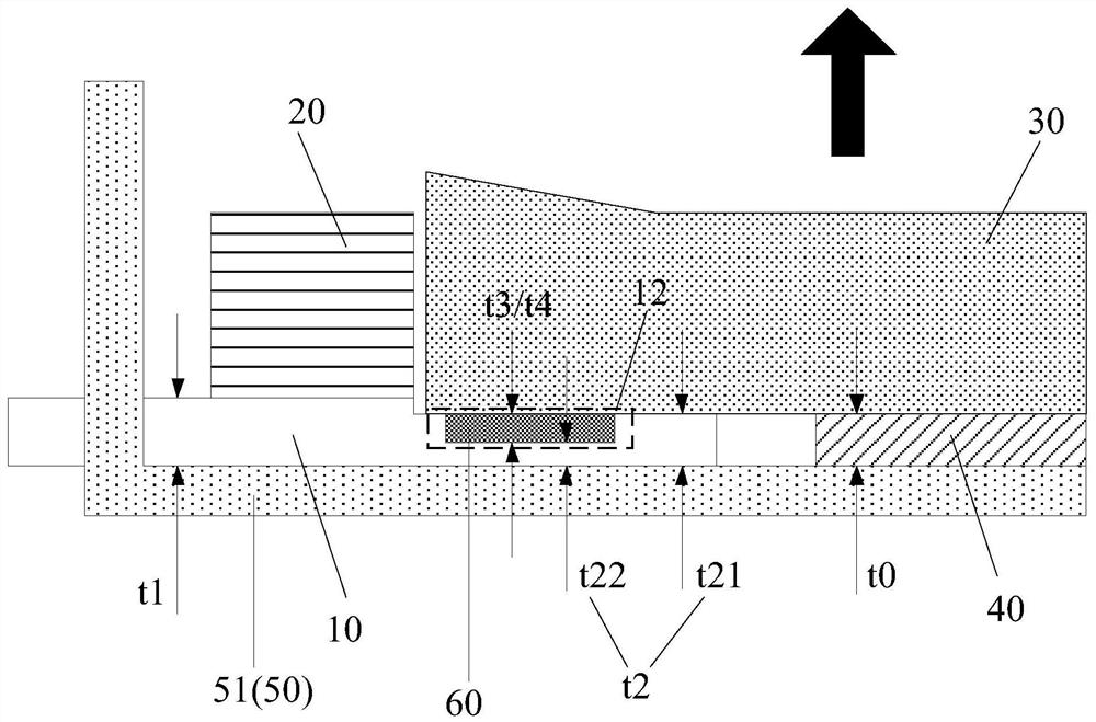
[0026] Embodiments of the present invention provide a backlight module, such as Figure 2 to Figure 7 shown, where, figure 2 It is a schematic diagram of the structure of the backlight module when the flexible circuit board is provided with through holes, image 3 It is a schematic structural diagram of a backlight module when a flexible circuit board is provided with a first groove, Figure 4 It is a schematic structural dia...


PUM


Abstract

The invention discloses a backlight module and a display device, and relates to the technical field of display. In the embodiment of the present invention, by setting the thickness of the flexible circuit board in different areas, that is, the second thickness is smaller than the first thickness, the thickness of the flexible circuit board in the area corresponding to the overlapping area can be smaller than that in the area corresponding to the area other than the overlapping area. The thickness in the outer area is conducive to reducing the height difference between the surface of the flexible circuit board facing away from the light guide plate and the surface of the reflective sheet facing away from the light guide plate, thereby improving the problem of increased thickness in the local area of ​​the backlight module. , so that the thinning design of the backlight module and the thinning design of the display device can be realized.

Description

technical field [0001] The present invention relates to the field of display technology, in particular to a backlight module and a display device. Background technique [0002] The liquid crystal display generally includes a backlight module, and the display function can be realized by the backlight source provided by the backlight module. The backlight module generally includes a frame body 50, a light-emitting element 20, a flexible circuit board 10, a light guide plate 30, a reflection sheet 40 and other structures, so as to figure 1 The structure of the backlight module shown is an example, in which the light-emitting element 20, the reflection sheet 40, the light guide plate 30 and the part of the flexible circuit board 10 are located inside the frame body 50; the light-emitting element 20 is an edge-type light source and is fixed on the flexible A light bar is formed on the circuit board 10 ; the light guide plate 30 can be located on the light-emitting side of the li...

Claims


Application Information

Patent Timeline
Patent Type & Authority Patents(China)
IPC IPC(8): G02F1/13357G02B6/00
CPCG02F1/133615G02B6/0081
Inventor 刘远明
Owner XIAMEN TIANMA MICRO ELECTRONICS
Learn More