Composite insulator device with built-in piezo-resistance unit

A technology of composite insulators and varistors, applied in varistors, overvoltage protection resistors, resistors, etc. The problem of high comprehensive cost and other problems can be solved to solve the aging of resistors, reduce the risk of foreign objects being blown by strong winds, and achieve the effect of low cost

Pending Publication Date: 2019-08-02
CHINA ELECTRIC POWER RES INST
View PDF0 Cites 3 Cited by
  • Summary
  • Abstract
  • Description
  • Claims
  • Application Information

AI Technical Summary

Problems solved by technology

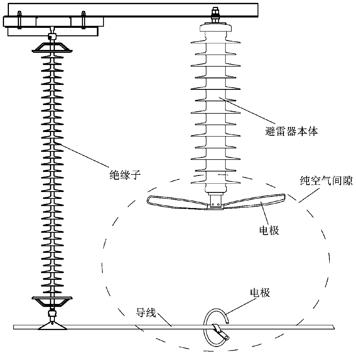
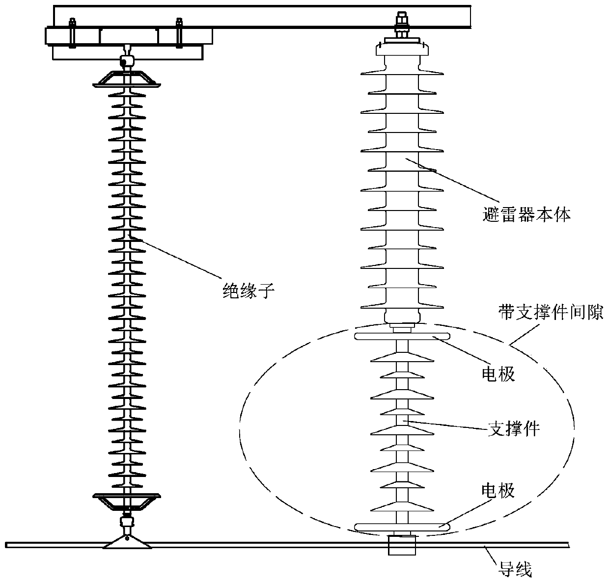
[0002] The existing out-of-band series gap surge arrester adopts the structure of the arrester body in series with pure air gap or with a support gap. Due to this kind of open outside series gap, the power frequency continuous flow stability is inherently insufficient and the current test conditions cannot support the development of long gap power frequency. Due to the limitations of freewheeling interruption test research, it is impossible to use the arc-extinguishing ability of the external series gap deeply and finely. As a result, the rated voltage value of the arrester body with the external series gap is relatively high, the device is large in size and weight, and the overall cost is high. On-site installation and construction The consumption of manpower and material resources is large; in the traditional way, the out-of-band series gap arrester and the line insulator are designed and produced independently of each other, assembled and assembled on site, the production process consumes a lot, the on-site installation operation is complicated, and the space occupied by the arrester is reduced. to adversely affect
The above-mentioned deficiencies lead to the high overall cost of lightning protection when using out-of-band series gap arresters in current projects

Method used


Image

  • Composite insulator device with built-in piezo-resistance unit
  • Composite insulator device with built-in piezo-resistance unit
  • Composite insulator device with built-in piezo-resistance unit

Examples


Embodiment Construction

[0033] Exemplary embodiments of the present invention will now be described with reference to the accompanying drawings. However, the present invention can be implemented in many different forms and is not limited to the embodiments described herein. These embodiments are provided to disclose the present invention in detail and completely. Invention and fully convey the scope of the present invention to those skilled in the art. The terms in the exemplary embodiments shown in the drawings do not limit the present invention. In the drawings, the same units / elements use the same reference signs.

[0034] Unless otherwise specified, the terms (including scientific and technological terms) used herein have the usual meanings to those skilled in the art. In addition, it is understandable that the terms defined in commonly used dictionaries should be understood as having consistent meanings in the context of their related fields, and should not be understood as idealized or overly for...


PUM

PropertyMeasurementUnit
diameteraaaaaaaaaa
lengthaaaaaaaaaa
areaaaaaaaaaaa

Abstract

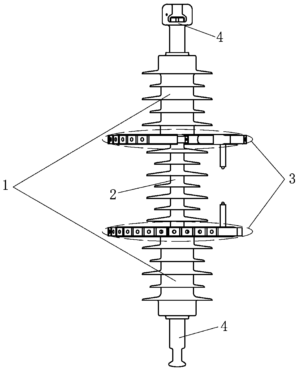
The invention discloses a composite insulator device with a built-in piezo-resistance unit. The composite insulator device comprises the piezo-resistance unit, an insulating pillar, enhanced blowout gap units and installation hardware; the piezo-resistance unit comprises a piezo-resistance subunit core, an insulating core rod and an insulating sheath; each enhanced blowout gap unit comprises a blowout cavity, an insulated support member and a gap electrode; and the enhanced blowout gap units are fixedly installed in the two ends of the insulating pillar or arranged uniformly along the axial direction of the insulating pillar. A lightning arrester is integrated with an insulator, the rated voltage of the piezo-resistance unit is reduced by using the high arc extinguishing capability of theenhanced blowout gap unit, and the device is mini, light and cheap; and the device is assembled while leaving the factory, onsite part adjustment and assembly are not needed, it is not required to strip an insulating layer of a lead when the device is connected with the insulating lead, and installation and construction are simple convenient.

Description

Technical field [0001] The invention relates to the technical field of lightning protection and grounding, in particular to a composite insulator device with a built-in varistor unit. Background technique [0002] Existing out-of-band series gap arresters use the structure of the arrester body in series with pure air gaps or with support gaps. Due to such open external series gaps, the power frequency continuous flow stability is inadequate and the current test conditions cannot support the development of long gap power frequency The limitation of continuous current interruption test research cannot make deep and refined use of the arc extinguishing ability of the external series gap, resulting in the high rated voltage of the current lightning arrester body with external series gap, large size and heavy weight, high overall cost, and on-site installation and construction High manpower and material resources; traditionally designed and produced out-of-band series gap arresters an...

Claims


Application Information

Patent Timeline
Patent Type & Authority Applications(China)
IPC IPC(8): H01B17/42H01B17/46H01C7/12H01T4/16H01T1/02H01T1/10
CPCH01B17/42H01B17/46H01C7/126H01T1/02H01T1/10H01T4/16
Inventor 沈海滨雷挺赵霞张兆华卢甜甜贺子鸣时卫东陈秀娟张搏宇康鹏吕雪斌
Owner CHINA ELECTRIC POWER RES INST
Why Eureka
Try Eureka