Safety cap spout providing accuracy of opening and easiness of check

A convenient and safe cover technology, applied in the direction of capping, safety devices, closures, etc., can solve the problems of decreased support force, poor assembly line of injection molding products, and high defective rate

Active Publication Date: 2019-08-02
中央塑胶技术有限公司
View PDF6 Cites 0 Cited by
  • Summary
  • Abstract
  • Description
  • Claims
  • Application Information

AI Technical Summary

Problems solved by technology

[0017] However, in this case, due to molding problems, the safety seal cannot be located directly under the inner cover, and since the safety seal is spaced from the lower part of the inner cover to its outside, it is located on the main body with a flow out. The locking protrusion at the lower end of the mouth of the hole locks with the locking groove of the safety seal either by pushing from the inside to the outside of the safety seal, or by pushing from the lower side to the upper side, but when set in this way, Considering the connection of the safety seal with the soft part, there is a problem that it cannot be locked and unsealed accurately due to the drop of the supporting force
[0018] Therefore, in order to prevent the idling phenomenon, a reinforcing rib is added between the safety seal and the inner cover, but when it is set in this way, there may still be a problem that some parts of the broken safety seal cannot be exposed to the outside
[0019] In addition, when such ribs are provided for support, there are not only difficulties in the mold or injection molding, but also poor assembly lines and low productivity of injection molded products, resulting in a high defective rate. Therefore, in mass production There are difficulties
[0020] Therefore, recently, in order to solve this problem, the lower edge of the annular wall portion constituting the outer cover is cut into a wave shape with valleys and valleys, so that the safety seal can be easily exposed. The shape may destroy the design, so there are still problems in actual use

Method used


Image

  • Safety cap spout providing accuracy of opening and easiness of check
  • Safety cap spout providing accuracy of opening and easiness of check
  • Safety cap spout providing accuracy of opening and easiness of check

Examples


Embodiment Construction

[0049] Hereinafter, the present invention will be described in detail with reference to the accompanying drawings.

[0050] first Figure 1 to Figure 9 is the shape of the spout of the safety cap according to the first embodiment of the present invention.

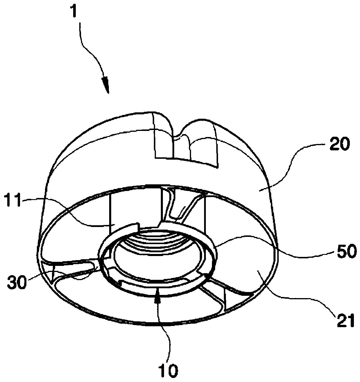
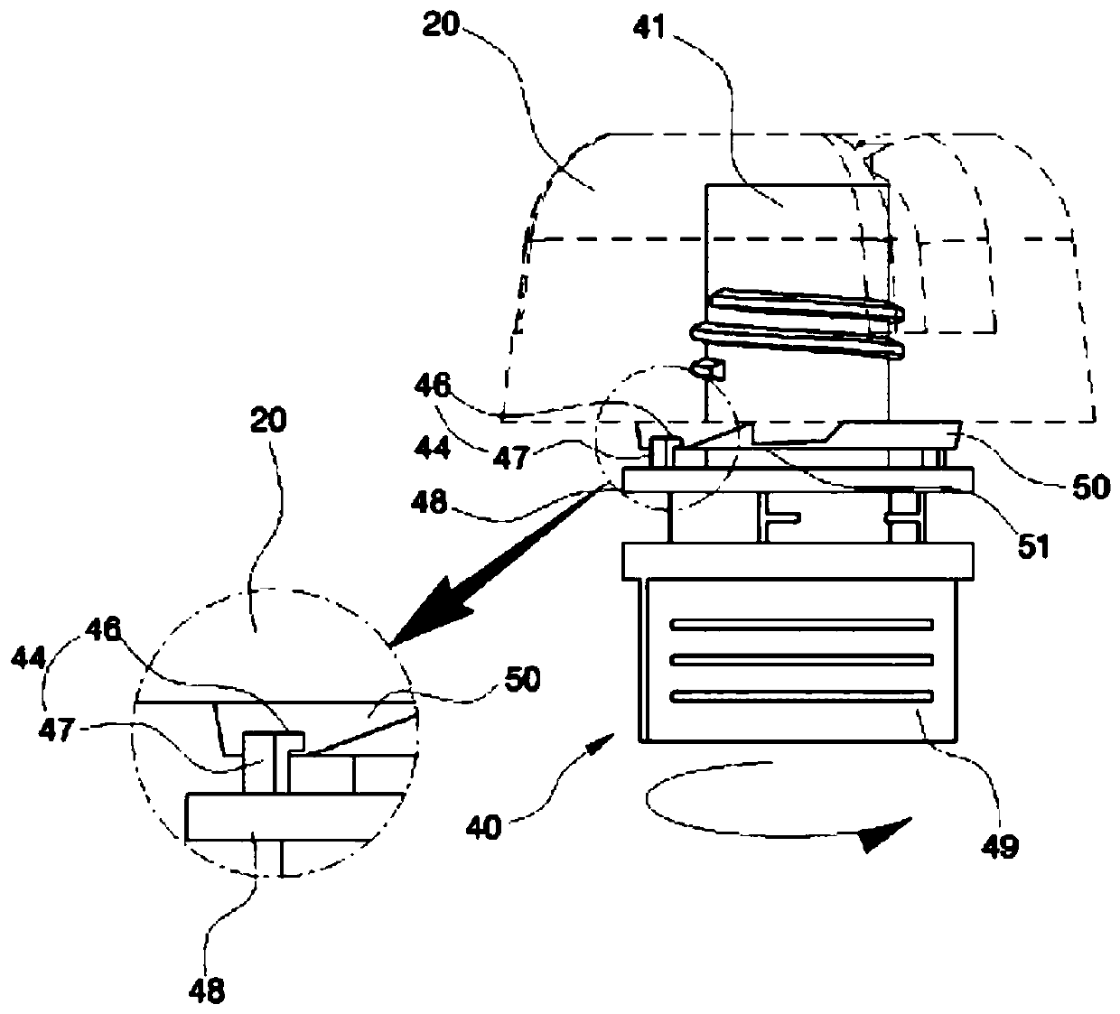
[0051] attached figure 1 It is a closure 1 of a fruit juice, various beverages, etc., especially a liquid bag container 100 for children, which is preferably a plastic injection-molded closure that is welded on the mouth 41 of the main body 40 of the bag container 100 through threads Way to tighten and unscrew.

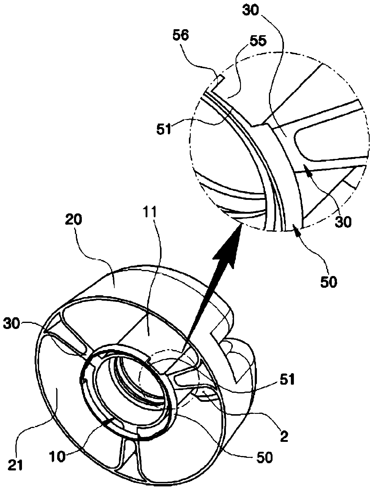
[0052] The cover 1 comprises, an inner cover 10 arranged along the central axis X and configured as a tubular body; an outer cover 20 connected with the outer wall of the inner cover 10 to the inner wall of the annular wall portion 21 through a cock 30; a vent hole 2. Since there are more than two cocks 30, a vent hole 2 is formed between the cocks.

[0053] That is to say, the annular wall portion 21 is spaced a...


PUM


Abstract

The present invention relates to a spout for a pouch container, the spout having a cap coupled in a one-touch manner to a body fused to a main body of the pouch container, and, particularly, to a spout, which is applied to a safety cap and includes a guarantee seal coupled to an interlocking protrusion of a body such that the interlocking protrusion is selectively interlocked with a plurality of interlocking grooves provided on the guarantee seal while the interlocking protrusion is located above the guarantee seal, to enable, when the pouch container is opened, the guarantee seal to be exactly cut while exposing the cut state to the outside of an external cap, thereby providing accuracy of opening and easiness of check.

Description

technical field [0001] The present invention relates to a safety cap spout that provides the accuracy of unsealing and the convenience of inspection. Specifically, the safety cap is connected to the main body welded with the body of the bagged container in a one-touch manner, especially when the safety cap When unsealing, the safety seal is accurately broken, so that the broken state can be exposed to the outside, thereby providing accuracy and inspection convenience when unsealing. Background technique [0002] In a conventional bag container, a spout for safely sealing and discharging the contents is used, the spout includes a main body provided with a welded portion welded to a certain position on the upper end of the bag container in an embedded manner, the welded portion The upper side is provided with an outflow hole, which protrudes outwardly from the upper end of the straw; the cover, used to seal the outflow hole of the main body, is usually detachably connected wit...

Claims


Application Information

Patent Timeline
Patent Type & Authority Applications(China)
IPC IPC(8): B65D41/34B65D75/58B65D55/02
CPCB65D41/3404B65D2213/00B65D75/5883B65D41/34B65D47/32
Inventor 权五准
Owner 中央塑胶技术有限公司
Why Eureka
Try Eureka