CT imaging system and CT imaging method

A CT imaging and CT image technology, applied in the field of biomedical imaging, can solve the problems of increasing the difficulty of image registration, disadvantageously distinguishing the tissue components of imaging objects, and the loss of X-ray attenuation information, so as to achieve the effect of increasing the difficulty of image registration

Active Publication Date: 2019-08-06
SHENZHEN INST OF ADVANCED TECH CHINESE ACAD OF SCI
View PDF9 Cites 1 Cited by
  • Summary
  • Abstract
  • Description
  • Claims
  • Application Information

AI Technical Summary

Problems solved by technology

This not only causes the loss of X-ray attenuation information, but also is not conducive to distinguishing the tissue components of the imaging object, and the reconstructed CT image, especially the soft tissue contrast is not obvious, which affects the imaging quality
A...

Method used


Image

  • CT imaging system and CT imaging method
  • CT imaging system and CT imaging method
  • CT imaging system and CT imaging method

Examples


Embodiment 1

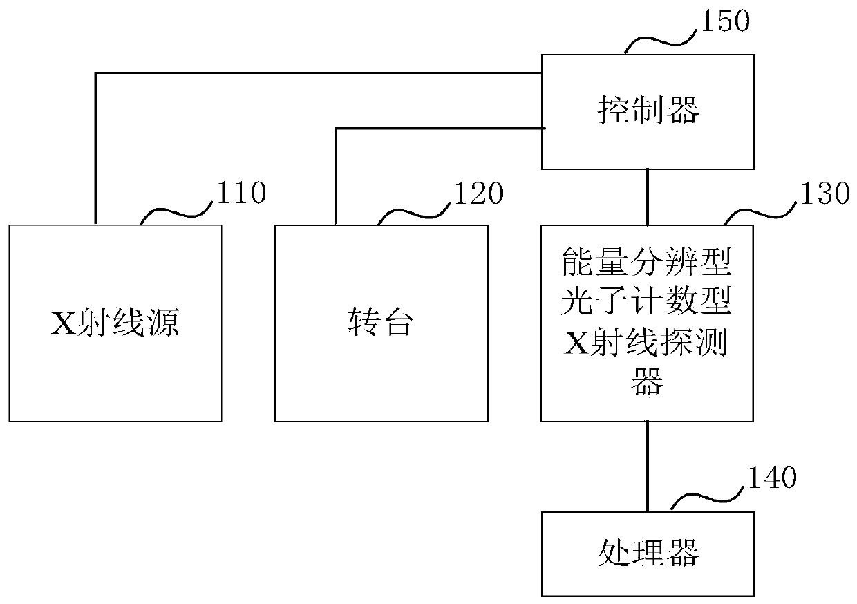
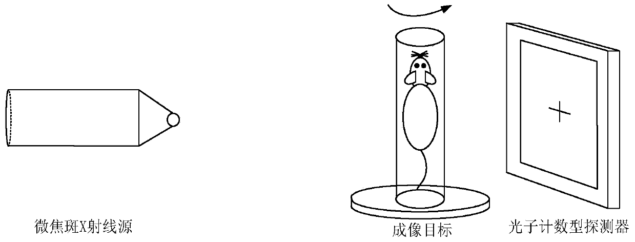
[0023] Figure 1a It is a structural schematic diagram of the CT imaging system provided in Embodiment 1 of the present invention. The CT imaging system provided in this embodiment can be used for imaging through energy-resolving photon-counting X-ray detectors, and is especially suitable for small animals through energy-resolving Type photon counting X-ray detector for imaging. Such as Figure 1a As shown, the CT imaging system includes: an X-ray source 110 , a turntable 120 , an energy-resolving photon-counting X-ray detector 130 and a processor 140 . in,

[0024] The turntable 120 is used to carry the imaging target, and carry the imaging target to rotate with the rotation axis of the turntable as the rotation center, wherein the imaging target is injected with a preset contrast agent;

[0025] X-ray source 110, configured to emit X-rays to the imaging target;

[0026] The energy-resolving photon-counting X-ray detector 130 is electrically connected to the processor 140, ...

Embodiment 2

[0050] figure 2 It is a flow chart of the CT imaging method provided by Embodiment 2 of the present invention. This embodiment is applicable to K-edge imaging of small animals, especially to a CT imaging system using an energy-resolving photon-counting X-ray detector. The method can be performed by the CT imaging system in the above-mentioned embodiment, and the device can be realized by hardware and / or software. ) to execute, specifically including the following steps:

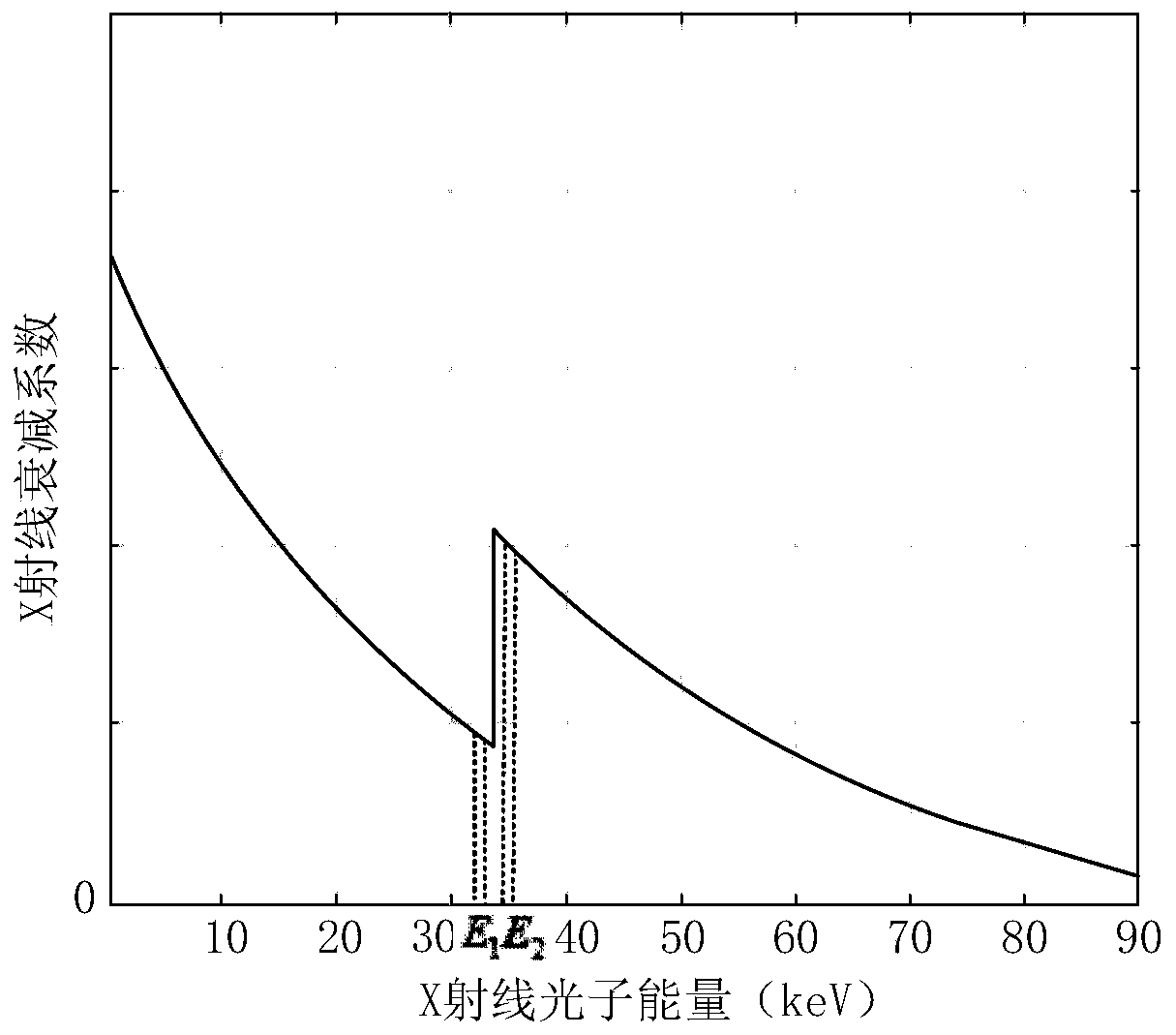
[0051] Step 201. Determine two energy threshold windows of an energy-resolving photon-counting X-ray detector according to a preset contrast agent injected into an imaging target.

[0052] It should be noted that the preset contrast agent in this embodiment is a contrast agent with known K-edge characteristics. According to the contrast agent with known K-edge characteristics, two energy threshold windows corresponding to the detector are determined, and each energy The threshold window corresponds to an e...


PUM


Abstract

The invention discloses a CT imaging system and a CT imaging method. The system includes: an X-ray source, a rotary table, an energy-resolving photon counting-type X-ray detector, and a processor, wherein the rotary table is configured to carry an imaging target, and carries the imaging target to rotate with a rotary table rotating shaft as a rotation center. The X-ray source is used for emittingX-rays to the imaging target; the energy-resolving photon counting-type X-ray detector is electrically connected to the processor for collecting the imaging targets passing through the X-rays, and theprojection data is sent to the processor in the projection data of the at least two energy intervals; the processor is configured to process the received projection data of the at least two energy intervals to generate the CT image of the imaging target. The technical scheme of the system achieves improving the contrast of the CT image and reducing the radiation risk.

Description

technical field [0001] Embodiments of the present invention relate to biomedical imaging technology, and in particular, to a CT imaging system and a CT imaging method. Background technique [0002] Medical CT can observe the conditions of various organs and tissues of the object in the living body. It performs images according to the different absorption and transmittance of X-rays by different tissues of the human body, and finds small lesions in the body. It is a widely used medical science. imaging device. [0003] In conventional X-ray CT imaging, the X-ray source produces multi-energy X-rays with a continuous energy spectrum, and the detector receives X-ray photons with different energies as a whole to reflect the average attenuation characteristics of X-rays. This not only causes the loss of X-ray attenuation information, but also is not conducive to distinguishing the tissue components of the imaging object, and the reconstructed CT image, especially the soft tissue ...

Claims


Application Information

Patent Timeline
IPC IPC(8): A61B6/03
CPCA61B6/035A61B6/44A61B6/4241A61B6/52
Inventor 葛永帅梁栋石伟张其阳刘新郑海荣
Owner SHENZHEN INST OF ADVANCED TECH CHINESE ACAD OF SCI
Why Eureka
Try Eureka