Sand core mold production surface coating coating device

A technology of surface coating and coating device, applied in the field of sand casting, can solve the problems of uneven coating, time-consuming and laborious manual painting, uneven distribution of coating on the surface of sand core mold, etc. The effect of avoiding paint build-up

Pending Publication Date: 2019-08-06
ANHUI QUANCHAI TIANHE MACHINERY
View PDF9 Cites 19 Cited by
  • Summary
  • Abstract
  • Description
  • Claims
  • Application Information

AI Technical Summary

Problems solved by technology

[0002] Sand core is the material used to manufacture mold cores in foundry production. It is composed of casting sand and sand binder. In order to improve the surface quality of castings, a layer of refractory coating is usually applied on the surface of sand cores to improve its surface resistance Thermal properties, chemical stability, resistance to liquid metal erosion, anti-sand sticking and other properties, the current coating methods often use manual brushing or spraying, manual brushing is time-consuming and laborious and will vary depending on the level of the brushing personnel The coating on the surface of the sand core mold is unevenly distributed, and the current spraying method is to fix the sand core mold and then spray it with a spray gun. However, the sand core mold is fixed so that the paint can only be sprayed on the sand core mold from one direction, which requires more The surface in contact with the sand core mold and the inner wall of the casting can be completely sprayed after the first spraying. However, repeated positioning and clamping of the sand core mold is required between multiple sprayings. There will be repeated spraying parts between each spraying, resulting in sand core mold surface Unevenness produces paint accumulation, so we propose a sand core mold production surface paint coating device to solve the above problems

Method used


Image

  • Sand core mold production surface coating coating device
  • Sand core mold production surface coating coating device
  • Sand core mold production surface coating coating device

Examples


Embodiment Construction

[0018] The following will clearly and completely describe the technical solutions in the embodiments of the present invention with reference to the accompanying drawings in the embodiments of the present invention. Obviously, the described embodiments are only some, not all, embodiments of the present invention. Based on the embodiments of the present invention, all other embodiments obtained by persons of ordinary skill in the art without making creative efforts belong to the protection scope of the present invention.

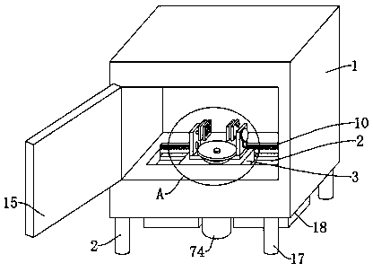
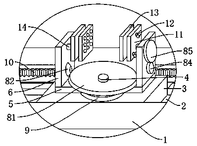
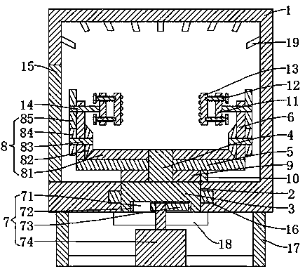
[0019] see Figure 1-5 , the present invention provides a technical solution: a surface coating coating device for sand core mold production, including a coating box 1, a plurality of spray guns 19 are installed on the top of the inner cavity of the coating box 1, and a slide is opened on the bottom plate of the inner cavity of the coating box 1. Slot 2, sliding and clamping slide plate 3 in chute 2, the top of slide plate 3 is fixedly installed with fixed sha...


PUM


Abstract

The invention discloses a sand core mold production surface coating coating device. The sand core mold production surface coating coating device comprises a coating box; a plurality of spray guns arearranged at the top of an inner cavity of the coating box; a sliding groove is formed in a bottom plate of the inner cavity of the coating box; the internal part of the sliding groove is in clamping connection with a sliding plate; a fixed shaft is arranged at the top of the sliding plate; the fixed shaft is in sleeving connection with a supporting plate; a connecting plate is arranged at the twoends of the supporting plate; the top of the connecting plate is in sleeving connection with an overturning shaft; a clamping piece is arranged at one end of the overturning shaft; a moving mechanismis arranged at the bottom of the sliding plate; a tooth ring is arranged at the bottom of the supporting plate; a long rack is arranged at the top of one side of the sliding groove; the tooth ring isengaged with the long rack; and an overturning mechanism is arranged between the overturning shaft and the fixed shaft. The moving mechanism drives the sliding plate to slide back and forth along thesliding groove; during sliding, the sliding plate enables the tooth ring to slide along the long rack, so that the tooth ring drives the supporting plate to rotate horizontally; the sand core mold rotates horizontally; meanwhile, the overturning mechanism performs linkage to drive the overturning shaft to rotate, the sand core mold vertically overturns, and a plurality of spray-coating surfaces ofthe sand core mold are spray-coated by the spraying guns in different directions, so that coating of the sand core mold can be completed through one-time spray-coating, and the coating is coated uniformly.

Description

technical field [0001] The invention relates to the technical field of sand casting, in particular to a sand core mold production surface paint coating device. Background technique [0002] Sand core is the material used to manufacture mold cores in foundry production. It is composed of foundry sand and sand binder. Thermal properties, chemical stability, resistance to liquid metal erosion, anti-sand sticking properties, etc., the current coating method often uses manual brushing or spraying, manual brushing is time-consuming and laborious and will vary due to the level of the brushing personnel The paint on the surface of the sand core mold is unevenly distributed, and the current spraying method is to fix the sand core mold and then spray it with a spray gun. However, the sand core mold is fixed so that the paint can only be sprayed on the sand core mold from one direction. The surface in contact with the sand core mold and the inner wall of the casting can be completely ...

Claims


Application Information

Patent Timeline
Patent Type & Authority Applications(China)
IPC IPC(8): B05B13/02B05B14/40
CPCB05B13/0235B05B13/0278B05B14/40
Inventor 王承标
Owner ANHUI QUANCHAI TIANHE MACHINERY
Why Eureka
Try Eureka