
Spinning wheel angle adjusting device used for paired wheel spinning equipment

An angle adjustment device and wheel spinning technology, applied in the field of angle adjustment devices, can solve the problems of low production efficiency, poor versatility and high mold cost, and achieve the effects of low maintenance cost, easy realization and easy processing

Inactive Publication Date: 2019-08-06
HARBIN INST OF TECH
View PDF3 Cites 6 Cited by
  • Summary
  • Abstract
  • Description
  • Claims
  • Application Information

AI Technical Summary

Problems solved by technology

[0003] The purpose of the present invention is to solve the problems of high mold cost, poor versatility and low production efficiency in the forming of large thin-walled bottom cover parts in the existing molded spinning equipment, and to provide a method for counter-wheel spinning equipment Rotary wheel angle adjustment device

Method used


Image

  • Spinning wheel angle adjusting device used for paired wheel spinning equipment
  • Spinning wheel angle adjusting device used for paired wheel spinning equipment
  • Spinning wheel angle adjusting device used for paired wheel spinning equipment

Examples


Embodiment Construction

[0024] The technical solutions in the embodiments of the present invention will be clearly and completely described below in conjunction with the accompanying drawings in the embodiments of the present invention. Obviously, the described embodiments are only a part of the embodiments of the present invention, rather than all the embodiments. Based on the embodiments of the present invention, all other embodiments obtained by those of ordinary skill in the art without creative work shall fall within the protection scope of the present invention.

[0025] The purpose of the present invention is to solve the problems of high mold cost, poor versatility and low production efficiency in the forming of large-scale thin-walled bottom cover parts in the existing mold spinning equipment, and to provide a counter-wheel spinning equipment Rotary wheel angle adjustment device.

[0026] Based on this, the rotating wheel angle adjusting device for counter-wheel spinning equipment provided by the...


PUM


Abstract

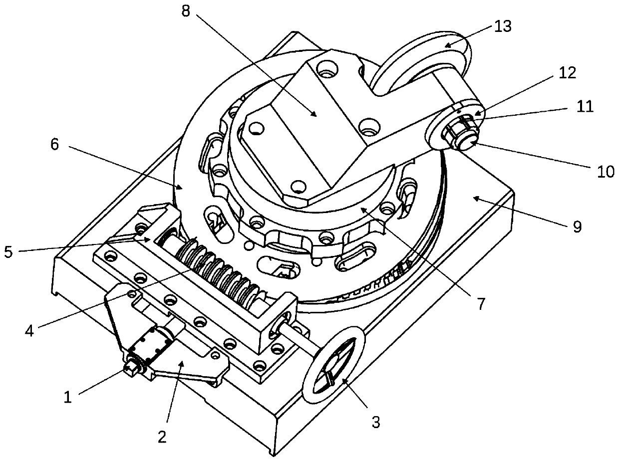
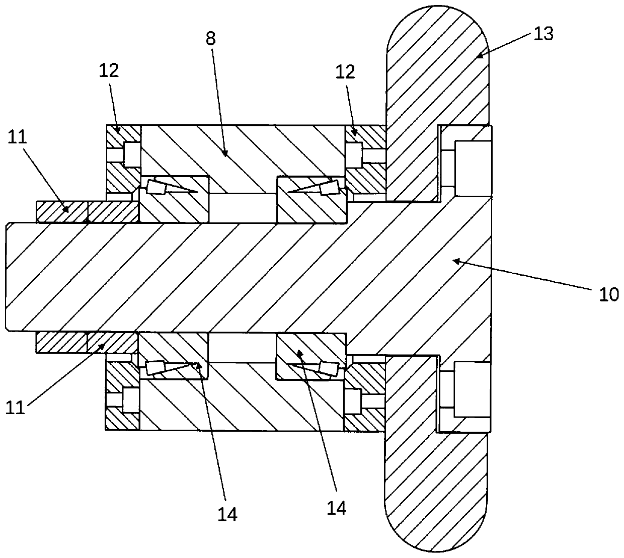
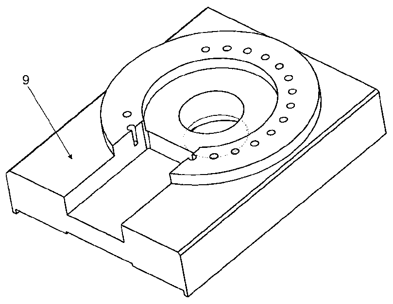
The invention discloses a spinning wheel angle adjusting device used for paired wheel spinning equipment. The problems that the mold cost of existing mold spinning equipment is high, universality is poor, and the manufacturing period is long are solved. A fixed groove is formed in a spinning wheel sliding table to be used for fixing a locking bolt seat; a jacking lead screw is mounted in the locking bolt seat; a worm bearing pedestal is connected with the spinning wheel sliding table through bolts; a hand wheel is mounted at one end of a worm; the worm cooperates with a worm wheel, and the spinning wheel angle is controlled by the worm and the worm wheel together; a rotating disc and the worm wheel are fixed, and synchronous motion is guaranteed; a spinning wheel frame is mounted on a spinning wheel seat, and a spinning wheel is mounted on a spinning wheel shaft inserted into the spinning wheel frame; bearing grooves capable of containing bearings are machined in the spinning wheel frame, the two bearings are mounted in the spinning wheel frame, and normal rotating of the spinning wheel shaft is guaranteed; spinning wheel sealing covers are mounted at the two ends of the spinning wheel frame; and axial locating of the spinning wheel shaft is achieved through a locking nut mounted at the tail end. The spinning wheel angle adjusting device is used for angle adjusting of a horizontal paired wheel spinning machine.

Description

Technical field [0001] The present invention relates to the technical field of angle adjusting devices, in particular to a rotating wheel angle adjusting device used for counter-wheel spinning equipment. Background technique [0002] The spinning forming process has unique advantages over welding and deep drawing due to its simple mold, flexible process, wide adaptability and other advantages. It is currently widely used in conical covers, spherical heads, curved busbar components, etc. Product manufacturing. Most of the traditional spinning forming processes require a spinning core mold, but when the size of the back cover structure is large, the coreless spinning process is widely used due to its low cost and short manufacturing cycle, such as the current large-scale head parts in the petrochemical industry A large number of coreless molds are used for one-step and two-step spinning forming. The current head spinning equipment can only form butterfly or spherical heads, and h...

Claims


Application Information

Patent Timeline
Patent Type & Authority Applications(China)
IPC IPC(8): B21D22/14
CPCB21D22/14
Inventor 徐文臣王少华王博陈家轩单德彬陈宇赖小明
Owner HARBIN INST OF TECH
Learn More