Overall mold entering structure for semi-formed steel bar mesh

A steel mesh and integral technology is applied in the field of semi-formed steel mesh integral moulding structure, which can solve the problems of low work efficiency and the like.

Pending Publication Date: 2019-08-06
苏州良浦节能新材料股份有限公司
View PDF0 Cites 2 Cited by
  • Summary
  • Abstract
  • Description
  • Claims
  • Application Information

AI Technical Summary

Problems solved by technology

[0004] In view of this, the present invention provides an integral die-entry structure for semi-formed steel mesh, aiming to solve the problem of low work efficiency caused by the fact that semi-formed steel mesh can only be positio...

Method used


Image

  • Overall mold entering structure for semi-formed steel bar mesh
  • Overall mold entering structure for semi-formed steel bar mesh
  • Overall mold entering structure for semi-formed steel bar mesh

Examples


Embodiment 1

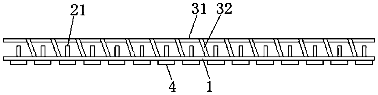
[0020] see Figure 1-2 , the figure shows a semi-formed reinforced mesh integral molding structure provided by Embodiment 1 of the present invention, which includes a transverse reinforcement component, a longitudinal reinforcement component, an intermediate connection component and a bottom positioning component, and the transverse reinforcement component includes several uniform The horizontal steel bars 1 arranged in a cloth, the longitudinal steel bar assembly includes several longitudinal steel bars 2 evenly distributed, the horizontal steel bars 1 and the longitudinal steel bars 2 are cross-connected, and are perpendicular to each other; the intermediate connection assembly includes reinforcing steel bars 31 and "V"-shaped connecting frames 32. The two ends of the bottom of the connecting frame 32 are respectively connected to the adjacent horizontal steel bars 1, and the top corners of the connecting frame 32 are connected to the reinforcing steel bars 31; The outermost...

Embodiment 2

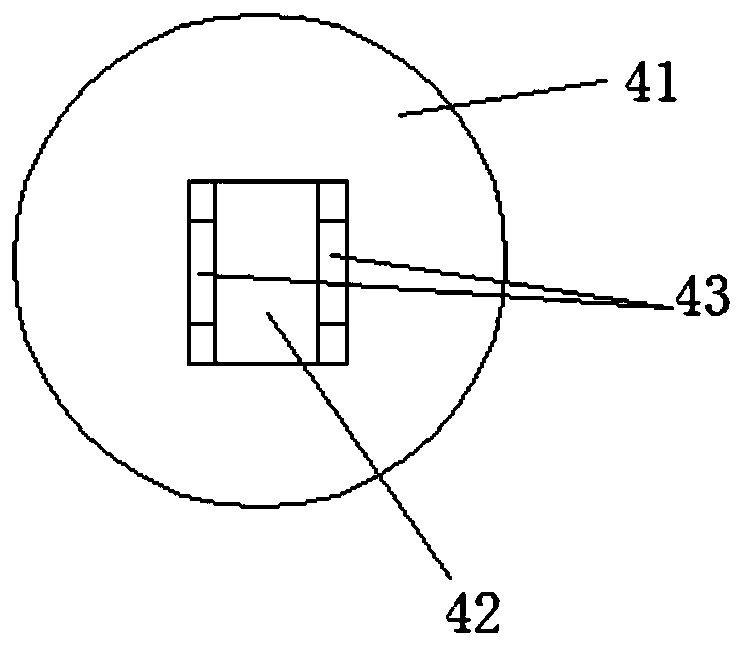
[0023] see Figure 3-5 , the figure shows a semi-formed reinforced mesh overall mold-in structure provided by Embodiment 2 of the present invention. On the basis of the above embodiment, this embodiment further makes the following technical solutions as improvements: positioning plate 4 includes a chassis 41 and a first positioning groove 42 and a second positioning groove 43 arranged on the chassis 41, the first positioning groove 42 and the second positioning groove 43 are vertically arranged, and the first positioning groove 42 is lower than the second positioning groove 43.

[0024] Through the above-mentioned further improvement, this embodiment has the following advantages compared with the prior art: a positioning plate 4 can simultaneously position the transverse steel bar 1 and the longitudinal steel bar 2 at the same time, quickly realize the positioning of the outermost steel bar, and improve the working speed .

Embodiment 3

[0026] see Figure 3-5 , the figure shows a semi-formed reinforced mesh overall molded structure provided by Embodiment 3 of the present invention. This embodiment further makes the following technical solutions as improvements on the basis of the above embodiments: first The widths of the positioning groove 42 and the second positioning groove 43 are both larger than the outer diameters of the transverse reinforcement bar 1 and the longitudinal reinforcement bar 2 .

[0027] Through the above further improvements, this embodiment has the following advantages compared with the prior art: the positioning accuracy of the bottom reinforcement is improved, and the overall quality of the reinforcement mesh is further improved.


PUM


Abstract

The invention provides an overall mold entering structure for a semi-formed steel bar mesh. The overall mold entering structure comprises a transverse steel bar assembly, a longitudinal steel bar assembly, a middle connecting assembly and a bottom positioning assembly; the transverse steel bar assembly comprises a plurality of transverse steel bars which are arrayed in an evenly distributed mode,and the longitudinal steel bar assembly comprises a plurality of longitudinal steel bars which are arrayed in an evenly distributed mode; the transverse steel bars and the longitudinal steel bars areconnected in a crossed mode and are perpendicular to each other; the middle connecting assembly comprises reinforcing steel bars and a V-shaped connecting frame; the two ends of the bottom of the connecting frame are connected with the adjacent transverse steel bars correspondingly, and the top corner of the connecting frame is connected with the reinforcing steel bars; and the bottom positioningassembly comprises a plurality of positioning discs, and the positioning discs are located at the junctions on the outermost sides of the transverse steel bars and the longitudinal steel bars and located at the bottommost position. By adopting the overall mold entering structure for the semi-formed steel bar mesh, manufacturing does not need to be conducted in a forming mold, production can be conducted at any moment, operation is convenient, the time is saved, and the working efficiency is improved.

Description

technical field [0001] The invention relates to a structure of a concrete prefabricated part, in particular to an integral molded structure of a semi-formed reinforcement mesh. Background technique [0002] PC is the English abbreviation of precast concrete (prefabricated concrete), which is called PC component in the field of housing industrialization. Such as prefabricated reinforced concrete column foundation, prefabricated steel structure steel column foundation, street lamp billboard column reinforced concrete foundation, prefabricated floor slab. Correspondingly, traditional cast-in-place concrete requires on-site molding, on-site pouring and on-site maintenance. Prefabricated concrete is widely used in construction, transportation, water conservancy and other fields, and plays an important role in the national economy. Especially for some municipal projects located in remote areas, which are not suitable for on-site pouring and forming, they are made into prefabrica...

Claims


Application Information

Patent Timeline
IPC IPC(8): E04C5/06B21F27/20B28B23/02
CPCE04C5/06B21F27/20B28B23/02
Inventor 秦振华刘红兵刘益贵浦玉蓉王晓夕魏中岳
Owner 苏州良浦节能新材料股份有限公司
Why Eureka
Try Eureka