Plastering device of building wall

A wall and building technology, applied in the direction of architecture and building structure, can solve problems affecting flatness, unbalanced force, and weak support, so as to improve the quality and efficiency of plastering, balance force, and avoid vibration Effect

Inactive Publication Date: 2019-08-06
LUAN VOCATIONAL TECHNOLOGICAL COLLEGE
View PDF1 Cites 10 Cited by
  • Summary
  • Abstract
  • Description
  • Claims
  • Application Information

AI Technical Summary

Problems solved by technology

This method of straightening is more accurate and ensures that the thickness of the wall after painting is consistent. Although the problem of uniform thickness of the wall after painting is solved in this application document, the plastering is carried out by vibrating motor vibration, which is easy to m

Method used


Image

  • Plastering device of building wall
  • Plastering device of building wall
  • Plastering device of building wall

Examples


Example Embodiment

[0034] Example one:

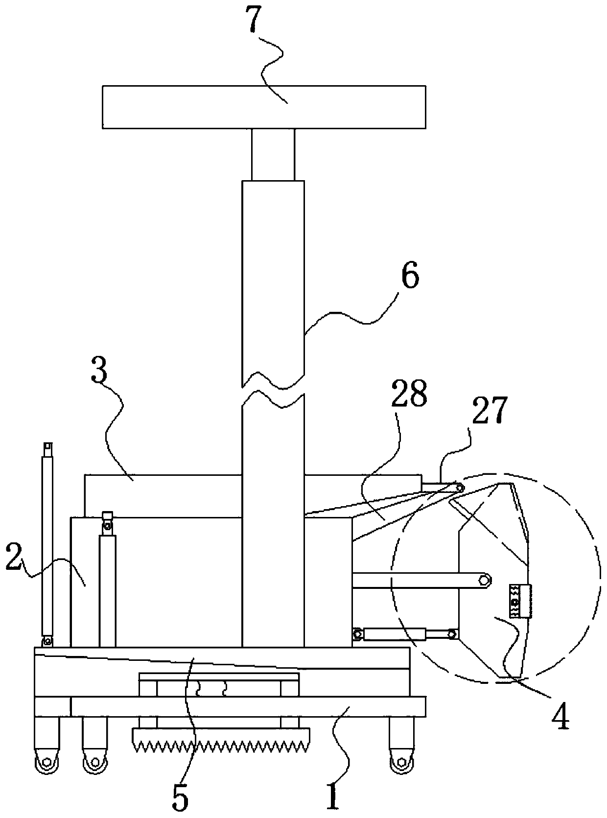
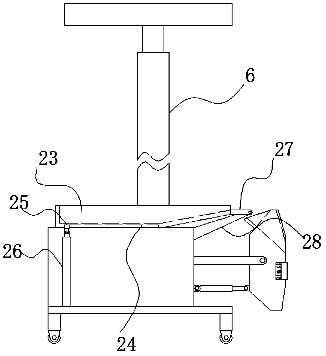
[0035] The feeding assembly 3 includes a hopper 23 located at the top of the box body 8. The end of the hopper 23 close to the plastering assembly 4 is fixedly connected with an extension plate 27, and the end of the extension plate 27 away from the hopper 23 is rotatably connected with the box body 8. The support rod 28, the bottom of the hopper 23 is provided with a chute 24 arranged along its length, and a slider 25 is slidably connected to the inside of the chute 24. The bottom of the slider 25 is hinged with a fourth drive mechanism fixedly connected to the top of the bottom plate 1 (26).

Example Embodiment

[0036] Embodiment two:

[0037] The plastering assembly 4 includes two groups of uprights 29 fixedly connected to the box body 8 and arranged in a horizontal direction. A plastering board 30 is movably sleeved between the two groups of uprights 29, and the plastering board 30 is located on the upright column 29 away from the box body 8. At one end, both ends of the plastering board 30 away from the box body 8 are provided with inclined plastering slope surfaces 36, and two groups of plastering slope surfaces 36 are symmetrically arranged along the plastering board 30, and the plastering board 30 is far away from the box body. A feeding channel 31 on the plastering slope 36 at the upper end of the plastering board 30 is opened on one side of the upper side of the plastering board 30. The feeding channel 31 is installed at the upper opening on the side away from the box body 8 with the plastering at the upper end of the plastering board 30. A flat scraper plate 32 on the slope 36, ...

Example Embodiment

[0038] Embodiment three:

[0039] The extrusion mechanism 35 includes an extrusion plate 38 slidably sleeved with the installation groove 34. The two ends of the extrusion plate 38 close to the box 8 are installed with baffles 39 slidingly connected to the adjacent sides of the plastering plate 30. The side of the baffle 39 close to each other is provided with a channel 40 arranged along its length. One end of the extrusion plate 38 extending into the mounting groove 34 is installed with a rotating rod arranged parallel to it through a bearing seat, and the outer ring of the rotating rod is fixed and sleeved There is a disc. The outer ring of the disc is fixedly connected with arc-shaped protrusions arranged in an array along its axis, and the protrusions are in contact with the pressing plate 38. The two ends of the rotating rod are fixedly sleeved with slaves located inside the channel 40. Moving sprocket, the outer ring of the driven sprocket is linked with a chain of annular ...


PUM


Abstract

The invention belongs to the technical filed of plastering, and particularly relates to a plastering device of a building wall. According to the following scheme, the plastering device includes a bottom plate, a driving assembly is arranged at the top of the bottom plate, a feeding assembly is arranged at the top of the driving assembly, a plastering assembly located in an discharging opening of the feeding assembly is mounted at one end of the driving assembly, locating frames fixedly connected with the top of the bottom plate are mounted at the bottoms of the output ends of the two sides ofthe driving assembly, supporting assemblies are mounted on the sides, away from each other, of the two sets of locating frames, the interiors of the locating frames sleeve extensible assemblies, and the same top abutting against frame is mounted between the tops of the two sets of the extensible assemblies. According to the plastering device of the building wall, fixing solidity of the whole plastering device is improved to avoid shaking of the plastering device during running, the accuracy of plastering is improved, the problem that when a traditional plastering device uses a vibration mode for plastering, imbalance stress is between a plastering board and the wall is changed is changed, so that a plastering layer is overall flat and has balance stress, plastering layer falling off is avoided, and the quality and efficiency of plastering are improved.

Description

technical field [0001] The invention relates to the technical field of plastering, in particular to a plastering device for building walls. Background technique [0002] The wall plastering machine is a machine that can automatically paint the wall. Due to the uneven ground, the column of the wall plastering machine is prone to tilt. Therefore, before starting the wall plastering machine, it is usually necessary to straighten the column of the wall plastering machine. The traditional operation method is generally that one worker presses a plate on the wall to be processed, and another worker pushes the wall plastering machine toward the wall to be processed until the column of the wall plastering machine touches the plate, and then adjusts straight to the end. However, the wall surface to be processed is often uneven. Even if the column is abutted against the flat plate, the column is not in a vertical state, resulting in inconsistent thickness of the painted wall; [00...

Claims


Application Information

Patent Timeline
IPC IPC(8): E04F21/08
CPCE04F21/08
Inventor 陆艳侠胡世斌张龙
Owner LUAN VOCATIONAL TECHNOLOGICAL COLLEGE
Why Eureka
Try Eureka