Split type static pressure gas bearing device with adjustable swing angle and for rotor static balance

A static pressure gas bearing and static balance technology, which is applied in the field of bearing devices and static pressure gas bearing devices, can solve the problems of large friction resistance, ball wear, and the inability to apply rotor static balance device, and achieve the effect of avoiding the wear of the shaft seat.

Active Publication Date: 2019-08-06
HARBIN INST OF TECH
View PDF5 Cites 9 Cited by
  • Summary
  • Abstract
  • Description
  • Claims
  • Application Information

AI Technical Summary

Problems solved by technology

[0006] In order to solve the problem that the existing rotor static balance device adopts rolling bearings as support, due to the high frictional resistance, long-term use will cause the balls to wear out, resulting in a decrease in the measurement accuracy of the rotor. However, most of the existing static pressure gas bearings are integrally manufactured. Can not be applied to the problem of the existing rotor static balance device, and provide a split static pressure gas bearing device with adjustable swing angle for rotor static balance

Method used


Image

  • Split type static pressure gas bearing device with adjustable swing angle and for rotor static balance
  • Split type static pressure gas bearing device with adjustable swing angle and for rotor static balance
  • Split type static pressure gas bearing device with adjustable swing angle and for rotor static balance

Examples


specific Embodiment approach 1

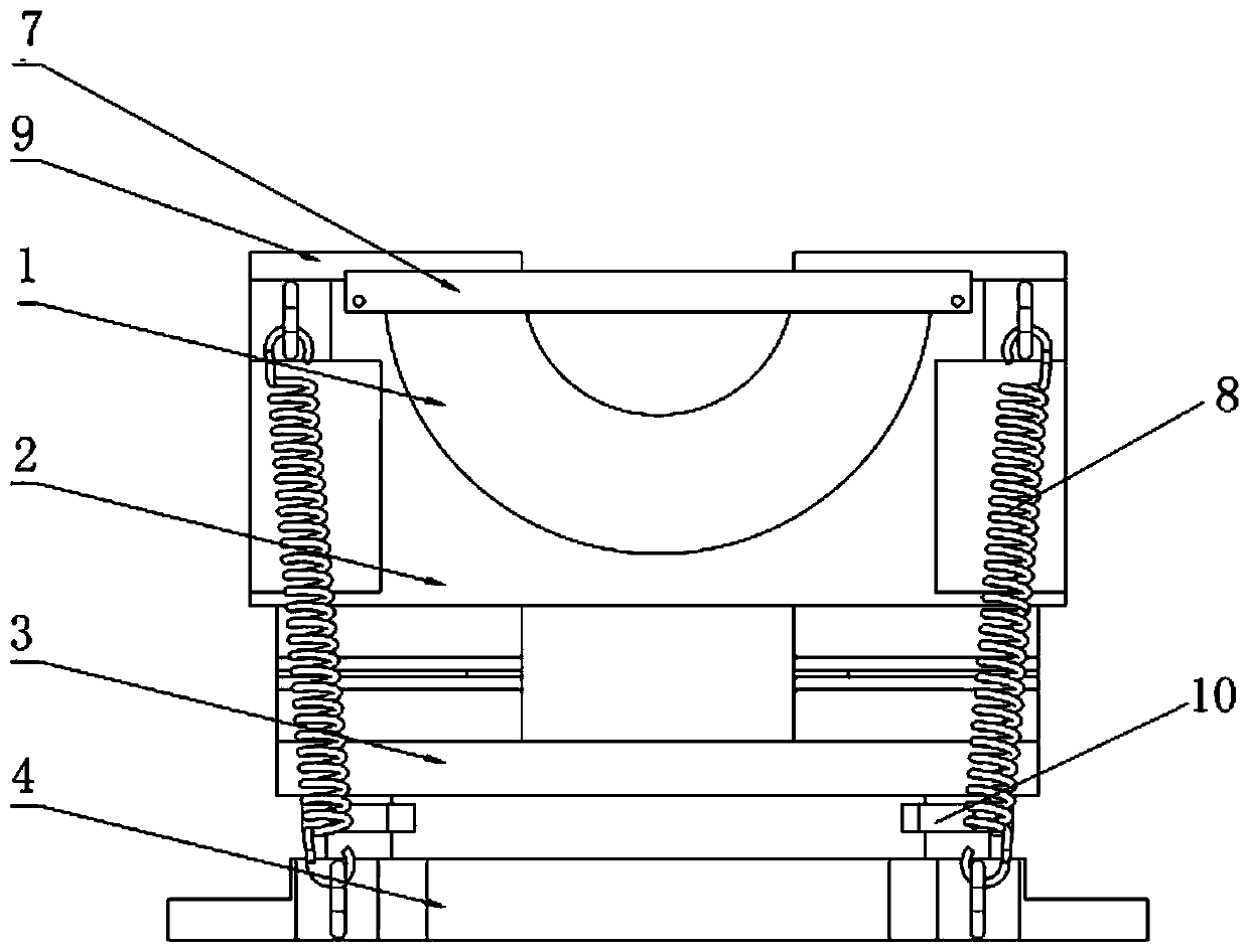
[0022] Specific implementation mode one: combine figure 1 , figure 2 , image 3 , Figure 4 and Figure 10 To illustrate this embodiment, this embodiment includes a shaft seat 1, an upper support 2, a lower support 3, a base 4 and an air intake passage 5;

[0023] A concave first semi-cylindrical surface is processed on the shaft seat 1, and the first semi-cylindrical surface faces upwards, and a plurality of air holes 1-1 are processed on the first semi-cylindrical surface, and the shaft seat 1 is fixed on the upper support On the base 2, a sealed air chamber 6 is provided between the shaft seat 1 and the upper support 2, and a plurality of air holes 1-1 communicate with the sealed air chamber 6, and the sealed air chamber 6 is connected to the external air supply device through the air intake channel 5 , the upper support 2 and the lower support 3 are hinged so that the axis of the semi-cylindrical surface can swing a certain angle along the vertical direction, and the ...

specific Embodiment approach 2

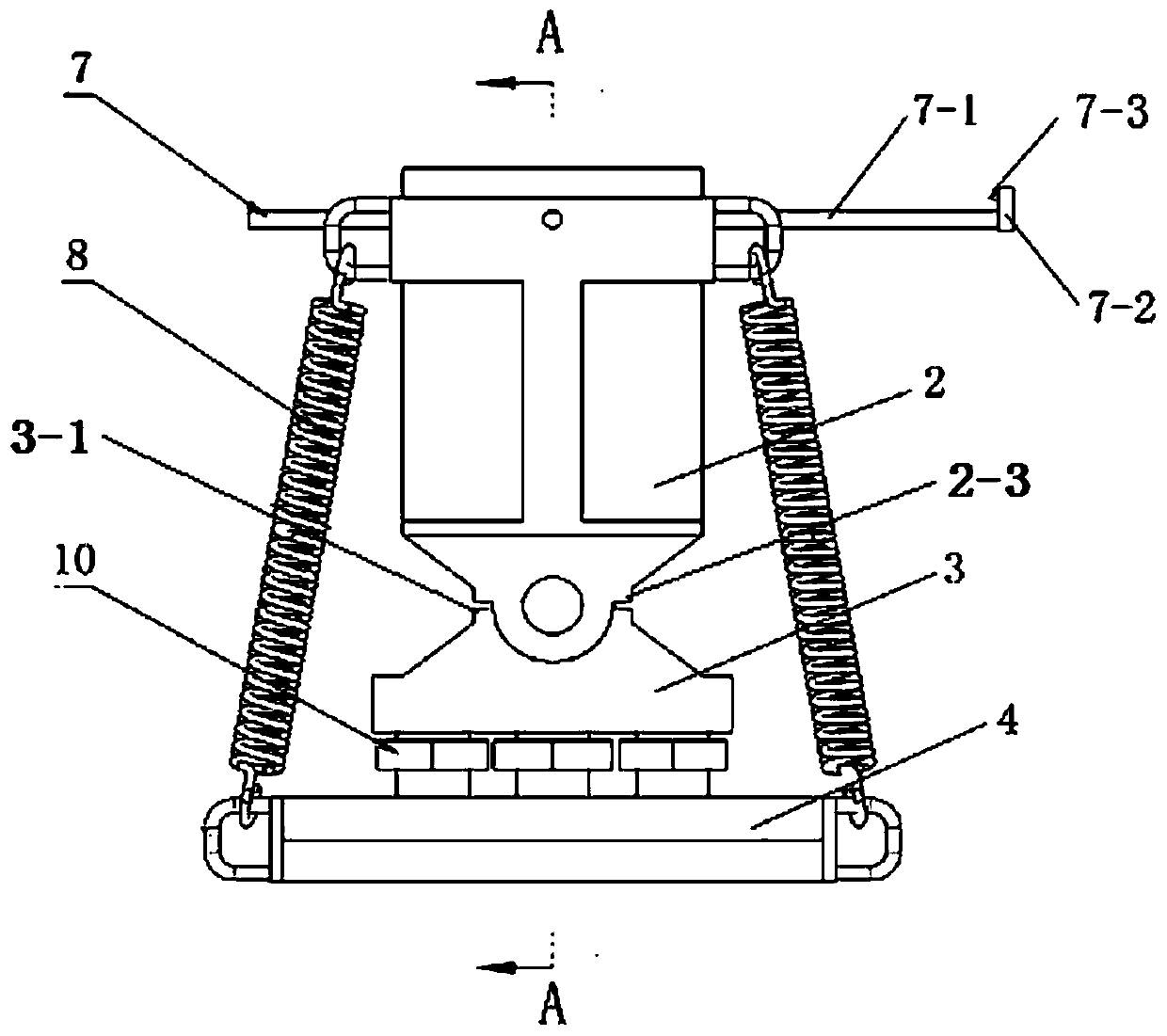
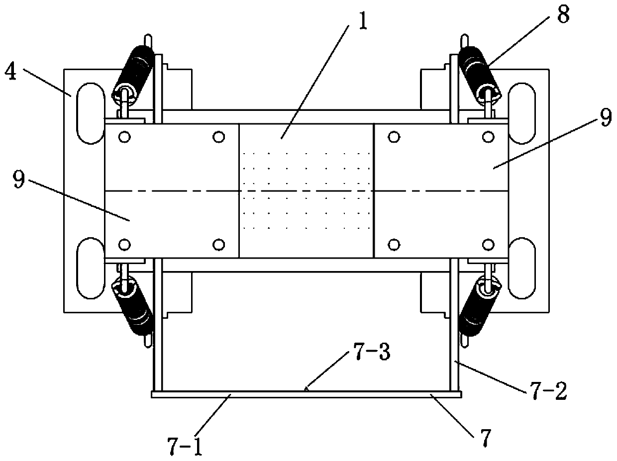
[0025] Specific implementation mode two: combination figure 2 and image 3 To illustrate this embodiment, this embodiment also includes an axial positioning device 7, the axial positioning device includes a baffle 7-1, two guide rods 7-2 and an axial limit shaft 7-3;

[0026] The two guide rods 7-2 are slidably arranged on the shaft seat 1, the baffle plate 7-1 is fixed on the two guide rods 7-2, the side of the baffle plate 7-1 facing the shaft seat 1 is processed with a bearing hole, and the bearing An axial limit shaft 7-3 is arranged in the hole, and a conical surface is processed on the axial limit shaft 7-3. The axis of the surface and the axes of the two guide rods 7-2 are parallel to each other, and the conical surface on the axial limit shaft 7-3 is concentric with the semi-cylindrical surface on the shaft seat 1. On the shaft seat 1 Two threaded holes are also processed on the top, and each threaded hole is provided with a top wire, and each top wire is pushed on ...

specific Embodiment approach 3

[0029] Specific implementation mode three: combination figure 2 and Figure 4 To illustrate this embodiment, the bottom of the lower support 3 in this embodiment is provided with three concave hemispherical surfaces, and the base 4 is processed with three threaded holes corresponding to the positions of the three concave hemispherical surfaces. Supporting screws 10 are provided in the holes, and the nuts of each supporting screw 10 are processed with outwardly convex hemispherical surfaces. The hemispherical surfaces on each supporting screw 10 match the hemispherical surfaces of each lower support 3, and the three The connecting line of any point on the respective axes of the two supporting screws 10 is a triangle.

[0030] With such arrangement, the supporting height of the axle seat 1 can be adjusted, and the axis of the axle seat 1 can be kept horizontal, which is convenient for installation.

[0031] Other compositions and connections are the same as in the first embod...


PUM


Abstract

The invention discloses a split type static pressure gas bearing device with an adjustable swing angle and for rotor static balance, and belongs to the field of rotor static balance detection. The split type static pressure gas bearing device with the adjustable swing angle and for rotor static balance is used for solving the problems that an existing rotor static balance device uses a rolling bearing as a support, due to the fact that the frictional resistance is high, rolling balls can be worn after the rolling bearing is used for a long time, the rotor measurement accuracy is reduced, and most of existing static pressure gas bearings are integrally manufactured and cannot be applied to the existing rotor static balance device. The split type static pressure gas bearing device with the adjustable swing angle and for rotor static balance comprises a bearing pedestal, an upper supporting base, a lower supporting base, a base and a gas inlet channel. A first semi-cylindrical face whichis inwards concave is processed on the bearing pedestal, and multiple gas holes are formed in the first semi-cylindrical face. The bearing pedestal is fixed to the upper supporting base, a sealed gascavity is formed between the bearing pedestal and the upper supporting base, the multiple gas holes communicate with the sealed gas cavity, and the sealed gas cavity is connected with an external gassupply device through the gas inlet channel. The upper supporting base and the lower supporting base are hinged so that the axis of the semi-cylindrical face can swing by a certain angle in the vertical direction. The lower supporting base and the base are connected together. The split type static pressure gas bearing device with the adjustable swing angle and for rotor static balance is suitablefor rotor static balance detection.

Description

technical field [0001] The invention relates to a bearing device, in particular to a split-type static pressure gas bearing device with adjustable swing angle for rotor static balance, belonging to the field of rotor static balance detection. Background technique [0002] In the process of manufacturing and installing rotor parts of rotating machinery, the rotor will produce unbalanced mass due to reasons such as material inhomogeneity, processing errors and assembly errors. During the rotation of the rotor, the unbalanced mass will cause the rotating machine to generate vibration and noise, seriously affecting the safety and reliability of the rotating machine. Therefore, all rotor parts of rotating machines need to be statically balanced. At present, rotor static balance detection devices usually use rotor static balance devices. [0003] The existing rotor static balancing device is provided with two sliding plates that can be adjusted up and down, and each sliding plate...

Claims


Application Information

Patent Timeline
Patent Type & Authority Applications(China)
IPC IPC(8): F16C32/06
CPCF16C32/0603F16C32/0666G01M1/04G01M1/12F16C32/0625F16C2300/02F16C32/0685F16C32/067
Inventor 刘占生张广辉于树博
Owner HARBIN INST OF TECH
Why Eureka
Try Eureka