Magnetic gear, magnetic gear driver and motor

A technology of magnetic gears and transmissions, applied in transmissions, belts/chains/gears, mechanical equipment, etc., can solve the problems of increasing the iron loss of magnetic gears, low transmission precision, and reducing the transmission efficiency of magnetic gears, so as to prolong the service life. , the effect of improving accuracy, reducing drag and magnetic gear wear

Active Publication Date: 2019-08-06
ZHUHAI PANSHI ELECTRONICS TECH CO LTD
View PDF12 Cites 6 Cited by
  • Summary
  • Abstract
  • Description
  • Claims
  • Application Information

AI Technical Summary

Problems solved by technology

However, today's magnetic gear transmission accuracy is low. Under high load or high-speed transmission, the transmission through magnetic coupling will increase the iron loss of the magnetic gear magnet and reduce the transmission efficiency of the magnetic gear.

Method used


Image

  • Magnetic gear, magnetic gear driver and motor
  • Magnetic gear, magnetic gear driver and motor
  • Magnetic gear, magnetic gear driver and motor

Examples


Embodiment Construction

[0029] Magnetic Gear Embodiment

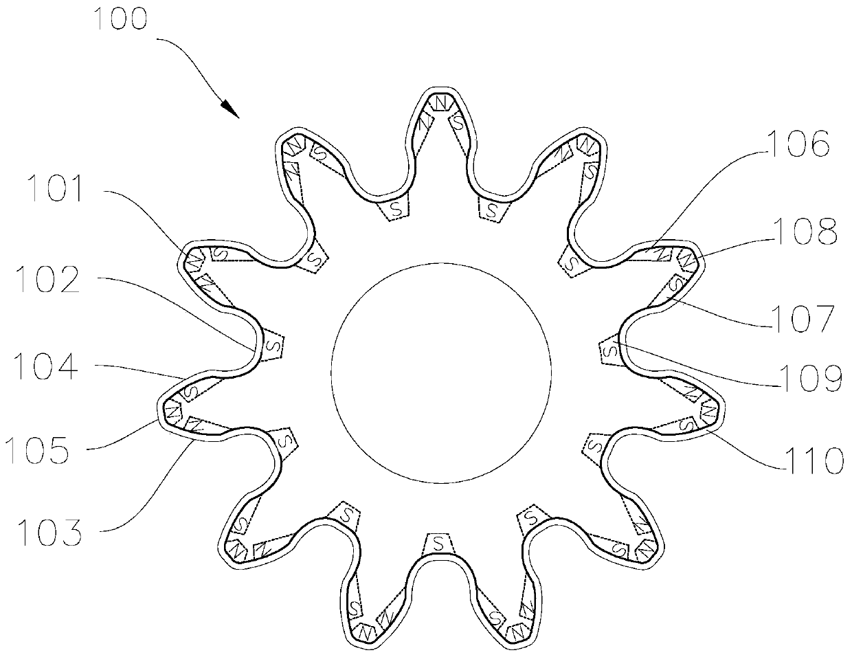
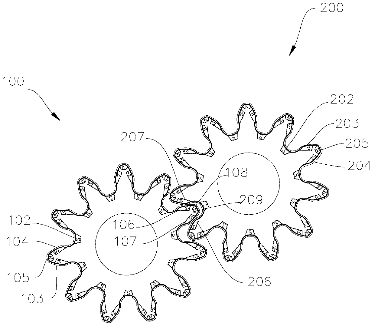
[0030] Such as figure 1 , figure 2 As shown, the magnetic poles N and S marked on the magnetic gear in the figure are the outer magnetic poles of the working surface of the gear teeth. The magnetic gear 100 includes gear teeth 101 and tooth slots 102 . The gear tooth comprises a first contact surface 103 , a second contact 104 and a tooth crest 105 . A first magnetic source 106 is provided at the first contact surface 103; a second magnetic source 107 is provided at the second contact surface 104; a third magnetic source 108 is provided at the crest 105; a fourth magnetic source is provided at the slot 102 109. The magnetic field strength of the first magnetic source 106 and the second magnetic source 107 is greater than the magnetic field strength of the third magnetic source 108 and the fourth magnetic source 109 .

[0031] The magnetic gear 100 is used in mesh with the magnetic gear 200 . The first magnetic source 106N pole of the fi...


PUM


Abstract

The invention provides a magnetic gear. The magnetic gear includes gear teeth and gear grooves. Each gear tooth includes a first contact surface, a second contact surface and a tooth tip. Each first contact surface is provided with a first magnetic source. Each second contact surface is provided with a second magnetic source. Each tooth tip is provided with a third magnetic source. Each gear groove is provided with a fourth magnetic source. The first magnetic sources and the second magnetic sources are used for generating repulsive force when two magnetic gears engage. The third magnetic sources and the fourth magnetic sources are used for generating attractive force when two magnetic gears engage with each other. The magnetic sources are arranged in the structure of the magnetic gear. Theforce of the magnetic sources facilitates the high-rotating speed drive of the magnetic gear. The magnetic sources arranged on the contact surfaces that the magnetic gears engage with each other areused for generating repulsive forces. The repulsive force among the magnetic sources helps to reduce the resistance and the wear of the magnetic gear and prolong the life of the magnetic gear. The magnetic sources arranged at the tooth tips and the gear grooves are used for generating attractive force, which facilitates the calibration of the engaging positions of the magnetic gear and improve theaccuracy of the drive of the magnetic gear.

Description

technical field [0001] The invention relates to a novel magnetic gear, and a magnetic gear transmission and a motor with the magnetic gear. Background technique [0002] Magnetic gears are wheel-shaped mechanical parts that transmit torque by the meshing of teeth. Due to the advantages of high transmission efficiency, accurate transmission ratio, and large power range, magnetic gear mechanisms are widely used in industrial products, and their design and manufacturing levels directly affect the quality of industrial products. The teeth of the magnetic gear are interlocked, and the magnetic gear will drive the other magnetic gear to rotate to transmit power. [0003] Today's magnetic gears are driven by meshing between two magnetic gears. There are contact surfaces with hard contact, and the load is large. When subjected to violent impact, it is easy to cause wear of the magnetic gears, reduce the transmission accuracy of the magnetic gears, and thus reduce the transmission e...

Claims


Application Information

Patent Timeline
Patent Type & Authority Applications(China)
IPC IPC(8): F16H55/17F16H55/06F16H55/08F16H49/00
CPCF16H55/17F16H55/06F16H55/08F16H49/005F16H2055/086
Inventor 何春旺
Owner ZHUHAI PANSHI ELECTRONICS TECH CO LTD
Why Eureka
Try Eureka